Ⅰ. Basic Definition and Core Objectives
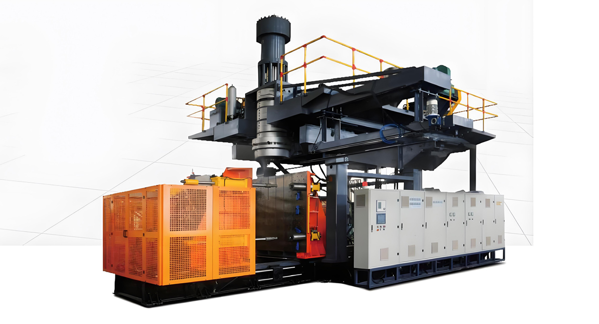
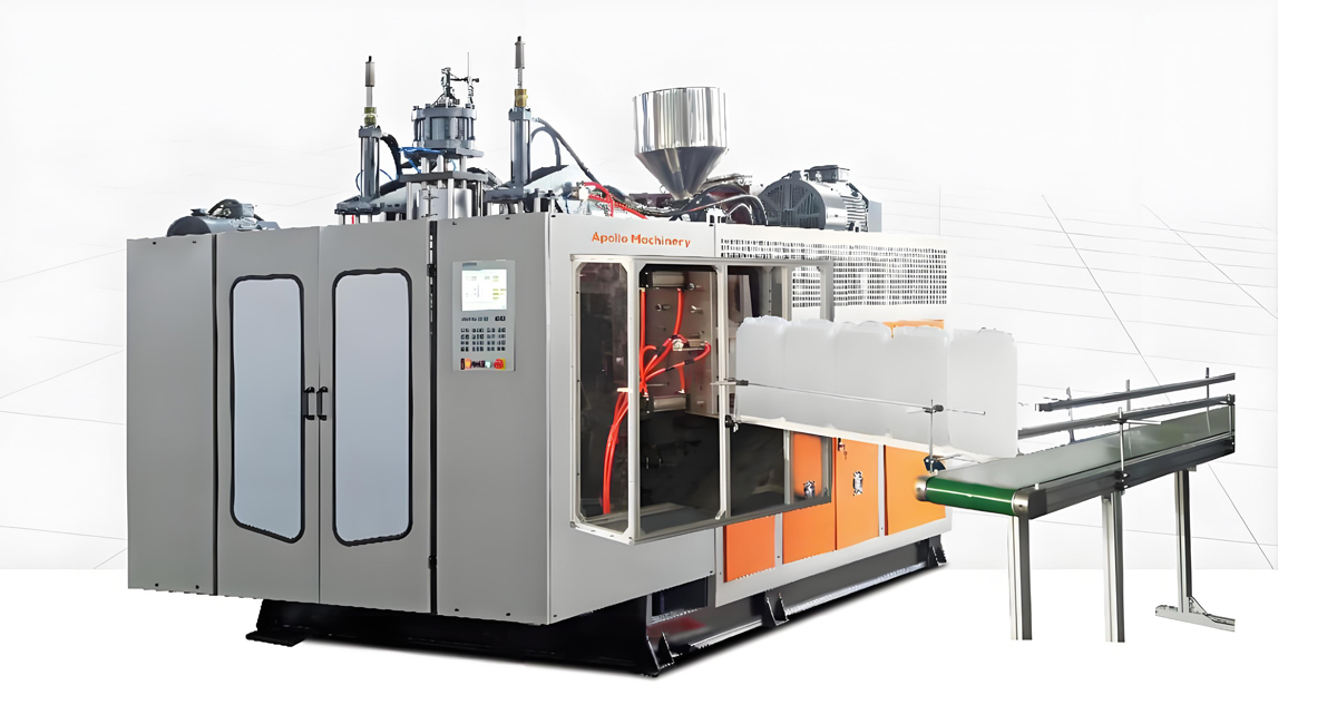
Extrusion blow molding machine is a core equipment for producing hollow plastic products through the process of “melt extrusion billet – compressed air inflation – mold cooling and shaping”. It is widely used in the large-scale production of hollow products such as beverage bottles, chemical barrels, automotive fuel tanks, packaging containers, etc. The core goal is to plasticize thermoplastic raw materials (such as PE, PP, PET, PVC, etc.) into continuous tubular billets through an extrusion system, and then use the mold cavity to restrict the shape. Through the blowing effect, the billets are pressed against the inner wall of the mold, and after cooling and solidification, hollow products that meet the design requirements are obtained.
According to different extrusion methods, extrusion blow molding machines are mainly divided into continuous extrusion blow molding machines (billet continuous extrusion, mold alternating work) and intermittent extrusion blow molding machines (billet quantitative extrusion, single completion of one or a group of products). The core principle of the two is the same, except for differences in billet preparation and mold coordination rhythm.
Ⅱ. Core components (strongly related to the working principle)
To understand the working principle, it is necessary to first clarify the core functional components and functions of the extrusion blow molding machine:
1. Extrusion system
The core function is to melt and plasticize solid plastic raw materials and continuously extrude tubular shaped blanks, mainly including:
Hopper: stores solid plastic particles, partially equipped with a drying device (removes moisture from raw materials to avoid bubbles in the product);
Screw and barrel: The core component of plastic plasticization, with a heating ring (segmented temperature control) on the outside of the barrel. The screw pushes the raw material through rotation, and with heating, the raw material gradually melts from solid particles into a uniform viscous flow state;
Mold head (machine head): The molten plastic is extruded through a circular flow channel to form a continuous tubular billet. The mold head is equipped with a core rod and a die, and the wall thickness uniformity of the billet can be controlled by adjusting the gap between the two.
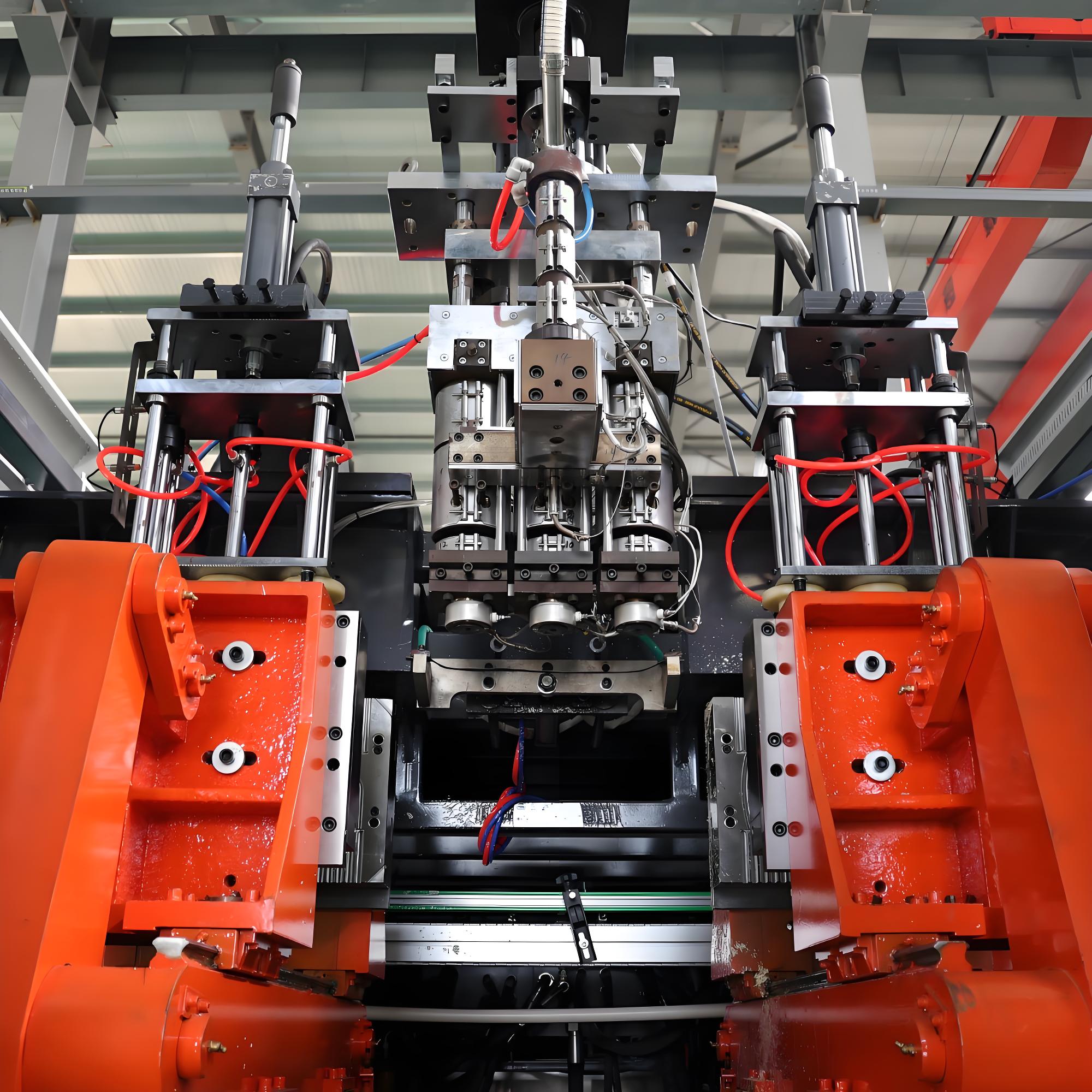
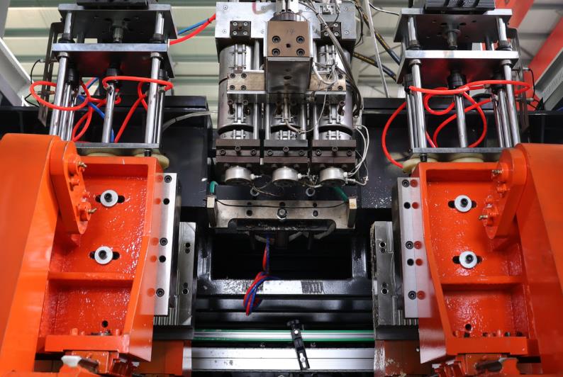
2. Mold closing system
The core function is to clamp the billet, provide a molding cavity, and cooperate with cooling, mainly including:
Mold: composed of left and right half molds, with a cavity inside that is consistent with the shape of the product (including details such as threads and patterns), and a cooling water channel and exhaust groove on the mold;
Mold closing mechanism: driven by hydraulic or servo motors, it achieves rapid closure and opening of the mold, and the closing force needs to be large enough to prevent the billet from overflowing from the mold gap during inflation;
Billet clamping device: located at the bottom of the mold, it clamps the bottom of the billet to form a sealed cavity when closed, providing a closed space for subsequent inflation.
3. Blow molding system
The core function is to inject compressed air into the billet and push it to stick to the mold, mainly including:
Blowing needle/nozzle: usually inserted into the interior of the billet from the top or bottom of the mold, it is an injection channel for compressed air;
Air compressor and stabilizing device: Provide compressed air with stable pressure (pressure range 0.2-1.0MPa, adjusted according to the size and thickness of the product), and the stabilizing device ensures uniform pressure during the inflation process to avoid product deformation.
4. Cooling system
The core function is to rapidly cool and solidify the inflated thermoplastic billet, mainly including:
Mold cooling water channel: Built around the mold cavity, it is filled with cooling water (water temperature controlled at 15-30 ℃), which takes away the heat of the billet through heat exchange;
Air cooling auxiliary device (some models): For thin-walled products or complex cavities, air cooling is used to accelerate surface cooling and improve production efficiency.
5. Control system
The core function is to coordinate the actions of various systems and accurately control process parameters, mainly including:
Temperature control system: segmented control of the heating temperature of the material barrel and mold head (adjusted according to the type of plastic, such as PE processing temperature of 150-220 ℃, PET processing temperature of 260-280 ℃);
Action control system: Control screw speed, mold closing speed, inflation pressure and time, cooling time and other parameters through PLC or industrial computer to ensure coordinated operation of each link;
Wall thickness control system (high-end model): By adjusting the gap between the die head and the core rod through a servo motor, the wall thickness of different parts of the billet is controlled in real time, improving product strength and material utilization.
Ⅲ. Complete workflow (taking continuous extrusion blow molding machine as an example)
The working process of an extrusion blow molding machine is a continuous cycle of coordinated actions of various systems, and the complete process can be divided into 5 core steps, which repeat in a loop to achieve mass production:
1. Raw material preparation and plasticization extrusion
Step 1: Add the dried solid plastic particles (such as HDPE for chemical drums and PET for beverage bottles) into the hopper, and the raw materials enter the gap between the screw and the barrel through the hopper;
Step 2: The material barrel is heated in sections (gradually increasing the temperature from the feeding section to the discharging section, such as 120-150 ℃ in the feeding section, 180-220 ℃ in the melting section, and 200-230 ℃ in the discharging section) to gradually soften and melt the plastic particles. At the same time, the screw rotates at a constant speed (usually 30-100r/min) to further promote uniform plasticization of the raw materials through shear force, avoiding the occurrence of unmelted particles;
Step 3: The molten plastic is continuously extruded through the annular flow channel of the die under the pushing pressure of the screw, forming a hollow tubular billet (the diameter of the billet is usually 1.2-1.5 times the maximum diameter of the product, the wall thickness is 2-5 times the wall thickness of the product, and the inflation allowance is reserved). The billet is suspended vertically below the die.
2. Mold closing and billet positioning
Step 1: When the length of the extruded billet reaches the required product height (detected by photoelectric sensors or travel switches), the control system sends a signal, and the mold closing mechanism drives the left and right halves of the mold to quickly close;
Step 2: During the mold closing process, first clamp the top and bottom of the billet: the top clamping point is located below the mold head to ensure that the billet is sealed with the mold head; The bottom clamping point cuts and seals the billet, forming a hollow cavity with closed ends;
Step 3: After the mold is closed, the blowing needle is quickly inserted into the sealed area at the top of the billet to prepare for the subsequent injection of compressed air. At this time, the billet is completely confined inside the mold cavity.
3. Blow molding
Step 1: Inject compressed air at a set pressure into the interior of the billet through a blowing needle (the pressure is adjusted according to the product type: thin walled beverage bottles 0.3-0.6MPa, thick walled chemical drums 0.6-1.0MPa);
Step 2: The pressure of compressed air acts on the inner wall of the billet, pushing the thermoplastic billet to expand in all directions and gradually conform to the inner wall of the mold cavity. The shape of the billet is completely replicated by the mold cavity (including surface patterns, threads, markings, and other details);
Step 3: During the inflation process, the exhaust groove on the mold cavity exhausts the air between the billet and the mold to avoid defects such as dents, bubbles, or unclear patterns on the surface of the product caused by air residue. The inflation time is usually 1-5 seconds (adjusted according to the product wall thickness).
4. Cooling and shaping
Step 1: After the inflation is completed, the cooling system continues to supply cooling water to the mold water channel, quickly dissipating the heat of the billet through thermal conduction;
Step 2: During the cooling process of the billet, the molecular chains gradually arrange in a regular manner, transforming from a viscous state to a solid state, and its shape is fixed. The cooling time is a key parameter affecting production efficiency and product quality: insufficient cooling can lead to deformation and surface stickiness of the product after demolding; Excessive cooling can prolong the production cycle and reduce efficiency. The usual cooling time is 3-10 seconds (thin-walled products are shorter, thick walled products are longer);
Step 3: Some high-end models will adopt a “graded cooling” strategy during the cooling stage, quickly cooling the surface of the product first, and then slowly cooling the interior to avoid internal stress caused by excessive temperature difference between the inside and outside of the product.
5. Demoulding and product removal
Step 1: After cooling is completed, the control system sends a signal, and the mold closing mechanism drives the mold to open;
Step 2: The demolding mechanism (such as a ejector pin, demoulding template, or robotic arm) pushes or removes the cooled and solidified product from the mold cavity;
Step 3: After the product is taken out, it is necessary to manually or automatically trim the clamping flash at the bottom and the blowing needle mark at the top (some models are equipped with online trimming devices, which can be directly trimmed after demolding) to obtain the finished product; At the same time, after the mold is opened, the extrusion system continues to extrude new billets and enters the next production cycle.
Ⅳ. Key control points (core principles affecting product quality)
1. Quality control of preform plasticization
Principle: Uneven plasticization can lead to defects such as bubbles, unmelted particles, and uneven wall thickness in the product. This can be achieved by controlling the temperature of each section of the material barrel, screw speed, and back pressure;
Control logic: Excessive temperature can lead to plastic degradation, while insufficient temperature can result in insufficient plasticization; Excessive screw speed can lead to high shear heat generation, while too slow speed can result in low plasticization efficiency. Accurate matching is required based on the characteristics of the raw materials and product requirements.
2. Control of billet wall thickness
Principle: The uniformity of the billet wall thickness directly determines the final wall thickness accuracy of the product. Ordinary models achieve static control by adjusting the gap between the die head and the core rod; High end models adopt a “dynamic wall thickness control system”, which adjusts the gap in real time through servo motors to compensate for the problems of bottom thickness and top thickness caused by gravity sagging of the billet;
Application scenario: For large or irregular products (such as car fuel tanks), dynamic wall thickness control can increase the wall thickness of critical parts (such as stress points) and reduce the wall thickness of non critical parts, ensuring strength and saving materials.
3. Inflation pressure and time control
Principle: Insufficient inflation pressure can cause the billet to not fully adhere to the mold cavity, resulting in incomplete product shape and blurred surface patterns; If the pressure is too high, it may lead to a thin wall thickness or even rupture of the product;
Control logic: The inflation time needs to be matched with the cooling time to ensure that the billet cools and solidifies under pressure, avoiding premature release of pressure that may cause the product to rebound and deform.
4. Cooling temperature and time control
Principle: If the cooling water temperature is too high, it will prolong the cooling time and reduce production efficiency; Low water temperature can cause condensation on the surface of the mold, affecting the surface quality of the product;
Control logic: Adjust the cooling time according to the thickness of the product. Thick walled products can adopt a “gradual cooling” method to avoid internal stress caused by excessive temperature difference between the inside and outside, which may lead to cracking during subsequent use of the product.
Ⅴ. The differences in working principles of different types of extrusion blow molding machines
1. Continuous extrusion blow molding machine
Working principle characteristics: The extrusion system continuously extrudes the billet, and the mold closing system adopts a “dual mold alternating work” mode (that is, when one mold is closed for inflation and cooling, the other mold is opened for demolding and ready to receive the next section of billet), with high production efficiency (suitable for mass production of simple shaped products such as beverage bottles and mineral water buckets);
Core advantages: Continuous and uninterrupted extrusion of preforms, high output per unit time, relatively simple equipment structure, and low maintenance costs.
2. Intermittent extrusion blow molding machine
Working principle characteristics: The extrusion system adopts a “quantitative extrusion” method, which uses the reciprocating motion of a plunger or screw to extrude a fixed length and volume of billet each time. Then, the mold is closed, inflated, cooled, and demolded. After completing one cycle, the next extrusion is carried out;
Core advantage: Accurate quantification of parison, suitable for producing large, thick walled or complex shaped products (such as automotive fuel tanks, large chemical drums, and irregular hollow parts), can avoid the problem of gravity sagging caused by excessive length of parison during continuous extrusion, and has better wall thickness uniformity.
Ⅵ. Adaptability to typical application scenarios and working principles
Beverage bottle (PET material): Using a continuous extrusion blow molding machine, it achieves thin-walled, highly transparent, and high-yield production through high-temperature plasticization (260-280 ℃), low inflation pressure (0.3-0.5MPa), and rapid cooling (3-5 seconds);
Chemical drum (HDPE material): using intermittent extrusion blow molding machine to quantitatively extrude thick walled billets, with an inflation pressure of 0.6-0.8MPa and a cooling time of 10-20 seconds, ensuring uniform wall thickness, impact resistance, and chemical corrosion resistance of the product;
Automobile fuel tank (multi-layer co extruded material, such as PE/barrier layer/PE): using a multi-layer co extrusion intermittent blow molding machine, multiple extrusion systems simultaneously extrude different materials of preforms to form multi-layer composite pipe blanks, which are blown and cooled by molds to achieve fuel barrier function;
Small packaging bottles (PP material): using continuous extrusion blow molding machine, low-temperature flexible plasticization (180-200 ℃), inflation pressure 0.4-0.6MPa, suitable for producing thin-walled and easily extruded packaging containers.
The working principle of extrusion blow molding machine is essentially a continuous cycle process of “melting and plasticizing of thermoplastic – forming of tubular billet – inflation and shaping of compressed air – cooling and solidification”. The core is to transform solid raw materials into hollow products that meet design requirements through the coordinated control of various systems. The key lies in precise control of plasticizing temperature, billet quality, blowing pressure, and cooling time. Different types of extrusion blow molding machines (continuous/intermittent) adjust the billet extrusion method to meet the needs of different production volumes, sizes, and complexities of products. They are the core technical equipment for industrial production of hollow plastic products.
Comparison of working principles between electric extrusion blow molding machine and traditional hydraulic extrusion blow molding machine
Ⅰ. Core commonality: Consistent basic workflow
The core working principle framework of the electric extrusion blow molding machine (fully electric type) is completely the same as that of the traditional hydraulic extrusion blow molding machine (hydraulic type), both following the essential logic of extrusion blow molding: through the continuous cycle of “plastic melting and plasticization → tubular billet extrusion → mold closure and clamping → compressed air inflation → cooling and solidification → demolding and part taking”, hollow products are formed. The core objectives, plasticization and extrusion principles (heating and shearing plasticization of screw barrel), blowing and shaping principles (compressed air pushing the billet to stick the mold), and cooling and solidification principles (heat exchange in the mold water channel) of the two are not fundamentally different, and they are all applicable to the production of hollow products of various thermoplastic plastics such as PE, PP, PET, etc.
The core commonalities can be summarized as follows:
The principle of plasticization is consistent: solid plastic particles are transformed into a uniform viscous flow state through segmented heating of the material barrel and rotation and shearing of the screw;
Consistent molding logic: both rely on the mold cavity to limit the shape, and compressed air inflation is used to achieve the bonding of the billet with the mold;
The circulation process is consistent: all use “extrusion molding blowing cooling demolding” as the basic circulation unit to mass produce hollow products.
Ⅱ. Core Differences: Drive System and Power Transmission Principle
The fundamental difference between the two lies in the different principles of the power drive system – the electric type is based on “direct drive by servo motor”, while the traditional hydraulic type is based on “hydraulic oil transmission of power”. This difference directly leads to significant differentiation in the working principle, control accuracy, response speed and other key performance of each execution system.
1. Comparison of core driving principles
1.1 Traditional hydraulic extrusion blow molding machine: hydraulic oil as the power medium
Driving principle: By driving the hydraulic pump with a motor, mechanical energy is converted into pressure energy of hydraulic oil. Then, the flow direction, pressure, and flow rate of hydraulic oil are controlled by hydraulic valves, which drive the actuator components such as oil cylinders and hydraulic motors to move, thereby driving actions such as mold closing, extrusion, and needle blowing.
Power transmission path: motor → hydraulic pump → hydraulic oil (pipeline transportation) → hydraulic valve → oil cylinder/motor → actuator (mold/screw/blowing needle).
Key characteristics: Hydraulic oil has compressibility, and there are oil leaks, pressure losses, and heat losses during power transmission; The action control relies on the pressure balance of the hydraulic system, and the control accuracy is greatly affected by changes in oil viscosity and temperature.
1.2 Electric extrusion blow molding machine: directly driven by servo motor
Driving principle: Multiple independent servo motors are used as power sources to directly drive each actuator through precision mechanical transmission components (ball screws, synchronous belts, gears and racks), without the need for hydraulic oil as an intermediate medium. Electrical energy is directly converted into mechanical energy.
Power transmission path: servo motor → precision transmission component (ball screw/synchronous belt) → actuator (mold/screw/blowing needle).
Key feature: The servo motor can achieve real-time position and speed feedback through an encoder, forming a closed-loop control; Power transmission has no intermediate medium loss, high mechanical transmission accuracy, fast response speed, and is not affected by environmental factors such as temperature and viscosity.
2. Differences in the working principles of each core system
2.1 Extrusion System: Comparison of Screw Drive Principles
Traditional hydraulic type: The rotation of the screw is driven by a hydraulic motor, and the speed of the hydraulic motor is adjusted by controlling the flow rate of hydraulic oil. Due to the compressibility of hydraulic oil and the lag in flow control, the stability of screw speed is poor (fluctuation range ± 3-5 r/min), resulting in significant fluctuations in plasticizing pressure and insufficient consistency in billet quality (wall thickness deviation ± 3-5%).
Electric type: The screw is directly driven by a dedicated extrusion servo motor, and the motor speed is precisely controlled by pulse signals, with a speed fluctuation range of ≤± 0.1r/min. The closed-loop control of servo motors can compensate for load changes in real time (such as fluctuations in raw material viscosity), ensuring uniform plasticizing pressure and a billet wall thickness deviation of ≤± 1%, especially suitable for the production of thin-walled and high-precision products.
2.2 Clamping System: Comparison of Mold Drive and Pressure Control Principles
Traditional hydraulic type: The clamping action is driven by a hydraulic cylinder, and the clamping force is achieved through pressure regulation of the hydraulic system. Due to the compressibility of hydraulic oil and pipeline resistance, there is a lag in the closing speed of the mold (response time>0.5 seconds), and the accuracy of mold closing force control is low (fluctuation range ± 5-8%), which can easily lead to problems such as “mold damage caused by too tight mold closing” or “mold overflow caused by too loose mold closing”; Mold positioning relies on mechanical limit, with a repeat positioning accuracy of ± 0.5-1mm.
Electric type: The clamping action is synchronously driven by 2-4 servo motors through ball screws or gear racks, and the clamping force is precisely controlled by the motor torque (fluctuation range ± 1-2%). The real-time position feedback of the servo motor can achieve precise positioning of the mold, with a repeat positioning accuracy of ± 0.01-0.1mm; the closing response time is less than 0.1 seconds, which can achieve high-speed mold closing and smooth clamping, avoiding gravity sagging caused by slow mold closing speed of the billet.
2.3 Inflation System: Comparison of Blow Needle Drive and Pressure Control Principles
Traditional hydraulic type: The lifting action of the blowing needle is driven by a small hydraulic cylinder, and the inflation pressure is adjusted by a hydraulic valve to regulate the output pressure of compressed air. Due to the delayed response of the hydraulic system, the synchronization between the timing of needle insertion and the inflation pressure is poor, which can easily lead to poor sealing at the top of the billet or uneven inflation; The fluctuation range of inflation pressure is ± 0.05-0.1MPa.
Electric type: The blowing needle is driven by a dedicated servo motor, and the insertion position and speed can be precisely programmed and controlled. The synchronization error with the mold closing and extrusion actions is less than 0.05 seconds; The inflation pressure is fed back in real-time through electronic pressure sensors and accurately adjusted by PLC, with a fluctuation range of ± 0.01-0.03MPa, ensuring uniform inflation of the billet, clear surface patterns, and consistent wall thickness of the product.
2.4 Cooling System: Comparison of Auxiliary Drive Principles
Traditional hydraulic type: Auxiliary equipment such as cooling water pumps and fans are usually driven by ordinary asynchronous motors with fixed speed. The cooling water and air volume cannot be dynamically adjusted according to the thickness and production rhythm of the product, resulting in low cooling efficiency and long production cycles (especially for thick walled products).
Electric type: The auxiliary equipment is driven by a variable frequency servo motor, and the cooling parameters (water volume, air volume, cooling time) can be linked with the product production process and automatically optimized through PLC. For example, thin-walled products can reduce cooling intensity and shorten cooling time, while thick walled products can increase cooling intensity and prolong cooling time, achieving precise cooling and shortening the production cycle by 20-50% compared to hydraulic products.
2.5 Control System: Comparison of Instruction Execution and Feedback Principles
Traditional hydraulic type: adopts the control mode of “PLC+hydraulic valve group”, and the control signal is converted into pressure/flow changes of the oil through the hydraulic valve, which belongs to “indirect control”. Due to the compressibility and transmission delay of the oil, there is a lag in the execution of control instructions, and it is impossible to provide real-time feedback on the actual status of the actuator (such as the actual position of the mold and the actual speed of the screw), which belongs to semi closed loop control and relies on manual experience for adjustment.
Electric type: adopting the control mode of “industrial PC+multi axis servo controller”, the control signal directly drives the servo motor, and the motor encoder provides real-time feedback on position, speed, torque and other data, forming a fully closed-loop control of “command execution feedback correction”. The control system can automatically compensate for factors such as load fluctuations and changes in raw material characteristics, achieving precise optimization of process parameters without the need for frequent manual adjustments.
Ⅲ. Summary of the Essence of Core Differences
The difference in working principle between electric extrusion blow molding machine and traditional hydraulic type is essentially the difference in technical route between “direct transmission+closed-loop control” and “indirect transmission+semi closed loop control”:
Power transmission: The electric type eliminates the loss and lag caused by hydraulic oil as an intermediate medium, achieving direct conversion from electrical energy to mechanical energy, resulting in higher transmission efficiency and faster response;
Control logic: Electric type forms closed-loop control through real-time feedback of servo motors, achieving precise control of position, speed, and pressure, while hydraulic type relies on pressure balance of the hydraulic system, and control accuracy is constrained by environmental factors;
Performance derivation: The difference in driving principles directly leads to the advantages of electric models in accuracy, energy consumption, maintenance, environmental friendliness, etc., while hydraulic models rely on mature hydraulic technology and still have cost advantages in heavy-duty low-speed scenarios.
Ⅳ. Differences in application adaptability (based on principle characteristics)
Traditional hydraulic type: Due to its principle of heavy load characteristics (hydraulic oil can transmit large pressure), it is suitable for producing large thick walled products (such as chemical drums above 20L and large shaped parts). The initial equipment cost is low, but long-term operation consumes high energy and maintenance is complex. It is suitable for scenarios with low precision requirements (wall thickness deviation ≥ 3%) and slow production pace;
Electric type: Based on its principle advantages of precise control and high-speed response, it is suitable for producing thin-walled, high-precision, and high-yield products (such as medical bottles, food packaging bottles, and lightweight automotive components), especially suitable for clean workshops (zero leakage) and energy-saving scenarios. Although the initial investment is high, the long-term operating cost is lower and the efficiency is higher.
The core working principle framework of electric extrusion blow molding machine is the same as that of traditional hydraulic extrusion blow molding machine (both follow the basic process of extrusion blow molding), but the fundamental difference lies in the principle of the driving system – the former is based on “servo motor direct drive+closed-loop control”, while the latter is based on “hydraulic oil transmission power+semi closed loop control”. This difference leads to significant differentiation between the two in terms of power transmission efficiency, control accuracy, response speed, energy consumption, and maintenance, ultimately affecting their adaptability to application scenarios: hydraulic models rely on heavy load characteristics to adapt to large thick walled products, while electric models have become the mainstream choice for high-end, precision, and high-yield hollow product production due to their precise and efficient advantages.