
Definition
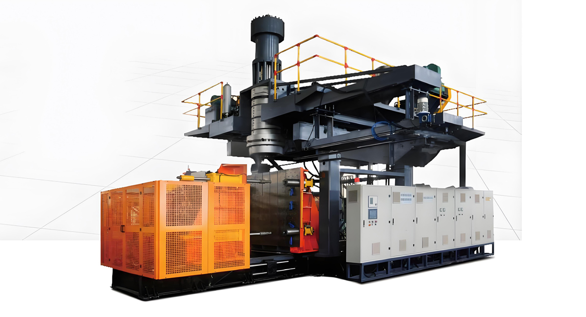
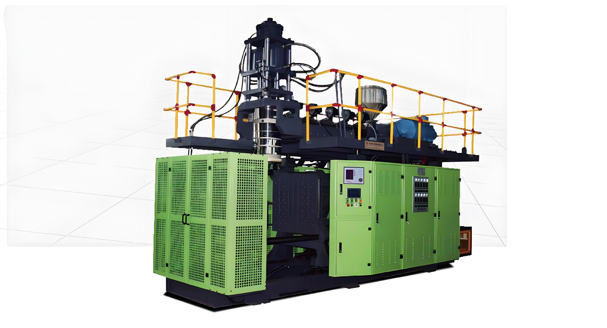
Extrusion blow molding machine (EBM Machine) is the core equipment in the field of hollow plastic container manufacturing, widely serving multiple industries such as food and beverage, daily chemical, chemical, pharmaceutical, etc. Its core function is to convert thermoplastic raw materials such as polyethylene (PE) and polypropylene (PP) into various hollow products; Its workflow is to melt and plasticize plastic particles through an extrusion system, extrude a tubular billet, wrap the billet with a mold, and blow compressed air to expand and fit the billet to the mold. After cooling and shaping, the finished product is obtained by trimming, achieving continuous and efficient production; This device has the advantages of strong production compatibility, convenient operation, controllable cost, and high stability of finished products. It can manufacture a variety of products from small packaging of a few milliliters to large containers of tens of liters, providing important hardware support for modern industrial production and daily life.
Classification
Extrusion Blow Molding Machines can be categorized in various ways, typically based on their structure, working principle, production capacity, application range, and drive system.
I. Classification by Parison Extrusion Method
This is the most fundamental classification, determining how the plastic melt forms the tubular parison.
- Continuous Extrusion Blow Molding Machine
- Working Principle: The plastic melt is continuously extruded from the extruder to form a continuous parison. When the parison reaches the predetermined length, the mold closes rapidly, clamping the top and bottom of the parison. Air is then blown into the parison, causing it to expand and conform to the mold cavity. The product is cooled and solidified before being ejected.
- Features: High production efficiency, suitable for mass production of small to medium-sized hollow products.
- Applications: Widely used for producing beverage bottles, cosmetic containers, pharmaceutical bottles, and various industrial containers (e.g., chemical drums, engine oil bottles).
- Intermittent Extrusion Blow Molding Machine
- Working Principle: This type of machine is usually equipped with an accumulator. The extruder first feeds the melt into the accumulator. Once a sufficient amount is accumulated, a plunger or screw injects the melt quickly and in one shot into the die head to form a parison.
- Features: Capable of delivering a large volume of melt in a short time, suitable for producing large, thick-walled, and complex-shaped hollow products.
- Applications: Primarily used for manufacturing large chemical drums (e.g., 200L drums), IBC ton containers, automotive fuel tanks, large toys, and plastic furniture.
II. Classification by Die Head Structure and Number
- Single-Station Blow Molding Machine
- Features a single die head and one set of molds.
- Relatively simple structure and lower cost, suitable for small and medium-sized enterprises or situations with fewer product types.
- Double-Station / Multi-Station Blow Molding Machine
- Equipped with two or more die heads and molds.
- Can produce multiple identical or different products simultaneously, significantly increasing production efficiency.
- Stations in multi-station machines typically include: parison forming, mold closing/blowing/cooling, mold opening/product ejection, etc., enabling automated continuous production.
III. Classification by Product Type and Special Structure
- Multi-Layer Blow Molding Machine
- Can extrude melts of two or more different materials simultaneously, which are combined through a special die head (co-extrusion die head) to form a multi-layer parison.
- Features: Combines the advantages of different materials, such as improved barrier properties (preventing oxygen and carbon dioxide permeation), cost reduction, and enhanced appearance.
- Applications: Mainly used for food packaging (e.g., ketchup bottles, cooking oil bottles), pharmaceutical packaging, and high-barrier chemical containers.
- Stretch Blow Molding Machine (SBM)
- A special type of blow molding machine that combines extrusion and stretching processes.
- Working Principle: First, a tubular parison is extruded by the extruder. It is then cooled to an appropriate temperature (below the melting point but above the glass transition temperature). Next, it is placed in a stretch mold, stretched axially by a stretch rod, then radially by blowing air, and finally cooled and solidified.
- Features: Products (e.g., PET bottles) produced have high strength, high transparency, high barrier properties, and are lightweight.
- Applications: Widely used for manufacturing PET bottles for carbonated drinks, mineral water, cooking oil, etc.
IV. Classification by Drive System
A very important modern classification, directly related to machine performance, energy consumption, maintenance, and cost.
- Hydraulic Blow Molding Machine
- Working Principle: The main moving parts of the machine, such as the mold clamping mechanism, accumulator plunger, and parison wall thickness control system, are all driven by a hydraulic system. A hydraulic pump provides high-pressure oil, and various actions are controlled through hydraulic cylinders and valves.
- Features: Powerful, capable of providing very high mold clamping and locking forces, stable operation, and strong overload protection.
- Advantages: Suitable for large, heavy-duty equipment, mature technology, and relatively low cost.
- Disadvantages: Complex structure, requires regular replacement of hydraulic oil and seals, risk of oil leakage, relatively high energy consumption, and high noise.
- Applications: Widely used in blow molding machines of various tonnages, especially large and heavy-duty equipment.
- All-Electric Blow Molding Machine
- Working Principle: All key movements of the machine are directly driven by servo motors. For example, the mold clamping mechanism is driven by a servo motor through a ball screw, the accumulator is driven by a servo motor, and wall thickness control is also precisely adjusted by servo motors.
- Features: Adopts a direct drive method of “servo motor + ball screw,” replacing traditional hydraulic cylinders.
- Advantages:
- Energy Saving and Environmental Protection: Energy consumption is typically 30%-50% lower than hydraulic machines.
- Clean and Tidy: No hydraulic oil leakage, resulting in a cleaner working environment.
- High Precision: High control precision of servo motors leads to better product repeatability and consistency.
- Fast Response: Fast motor response speed can improve production efficiency.
- Simple Maintenance: No need to handle hydraulic oil, resulting in low maintenance costs.
- Low Noise: Much lower noise during operation compared to hydraulic machines.
- Disadvantages: The cost of motors and transmission components can be very high when driving ultra-large tonnage equipment.
- Applications: Increasingly used in fields with high requirements for environmental protection, efficiency, and precision, such as food packaging and pharmaceutical packaging. With technological advancements, its application range is expanding to large equipment.
Comparison
To better understand the differences between hydraulic and all-electric drives, we can compare them as follows:
| Feature | Hydraulic Drive | All-Electric Drive |
|---|---|---|
| Power Source | Hydraulic pump and cylinder | Servo motor and ball screw/timing belt |
| Power Characteristics | Powerful, suitable for heavy loads | Precise power, flexible control |
| Response Speed | Relatively slow | Very fast |
| Energy Consumption | High (pressure must be maintained even during standby) | Low (power supplied on demand, small energy loss) |
| Maintenance | Complex (regular oil changes, leakage handling) | Simple (mainly lubrication and motor maintenance) |
| Cleanliness | Risk of oil leakage | No oil contamination, clean and environmentally friendly |
| Noise | High (hydraulic pump noise) | Low |
| Cost | Relatively low initial equipment investment | Relatively high initial equipment investment |
| Application Scenarios | Large, heavy-duty, cost-sensitive equipment | Medium and large equipment with high requirements for environmental protection, efficiency, and precision |
The choice of extrusion blow molding machine drive system mainly depends on your product characteristics, production scale, budget, and requirements for environmental protection and efficiency. Currently, all-electric drive is an important trend in the industry, especially as environmental and efficiency requirements increase.
Structure
A typical Extrusion Blow Molding Machine is a highly integrated system composed of several core components that work together to transform plastic pellets into various hollow products. Its structure can be divided into the following main sections based on functional modules:
I. Extrusion System
This is the “heart” of the extrusion blow molding machine, responsible for heating, melting, plasticizing solid plastic pellets, and extruding them continuously or intermittently to form a tubular parison.
- Hopper
- Function: Stores and uniformly feeds plastic raw material into the extruder.
- Features: Often equipped with drying and mixing devices to ensure the raw material’s dryness and uniformity, preventing defects like bubbles in the final product.
- Extruder
- Function: Heats, melts, shears, and mixes the plastic pellets from the hopper to create a homogeneous melt.
- Core Components:
- Screw: The central component of the extruder. It conveys material forward through rotation while shearing, compressing, and mixing it. The screw design (e.g., length-to-diameter ratio, compression ratio, thread profile) directly impacts plasticization quality and output rate.
- Barrel: Works in conjunction with the screw to form a closed chamber. The exterior of the barrel is typically fitted with heating bands and cooling fans for precise temperature control of the material.
- Drive System: Usually consists of a motor and a gearbox, providing rotational power to the screw.
- Die Head
- Function: Shapes the molten plastic melt from the extruder into a tubular parison of a specific shape and wall thickness through specialized flow channels and a die orifice.
- Core Components:
- Die Orifice: Determines the outer diameter of the parison.
- Mandrel: Determines the inner diameter and wall thickness of the parison.
- Wall Thickness Control System (WTC): For high-end equipment requiring precise control over product wall thickness, the die head incorporates an adjustable mandrel or valve pin driven by a servo motor. This system real-time adjusts the parison’s wall thickness distribution according to a preset program, ensuring uniform wall thickness in the final product.

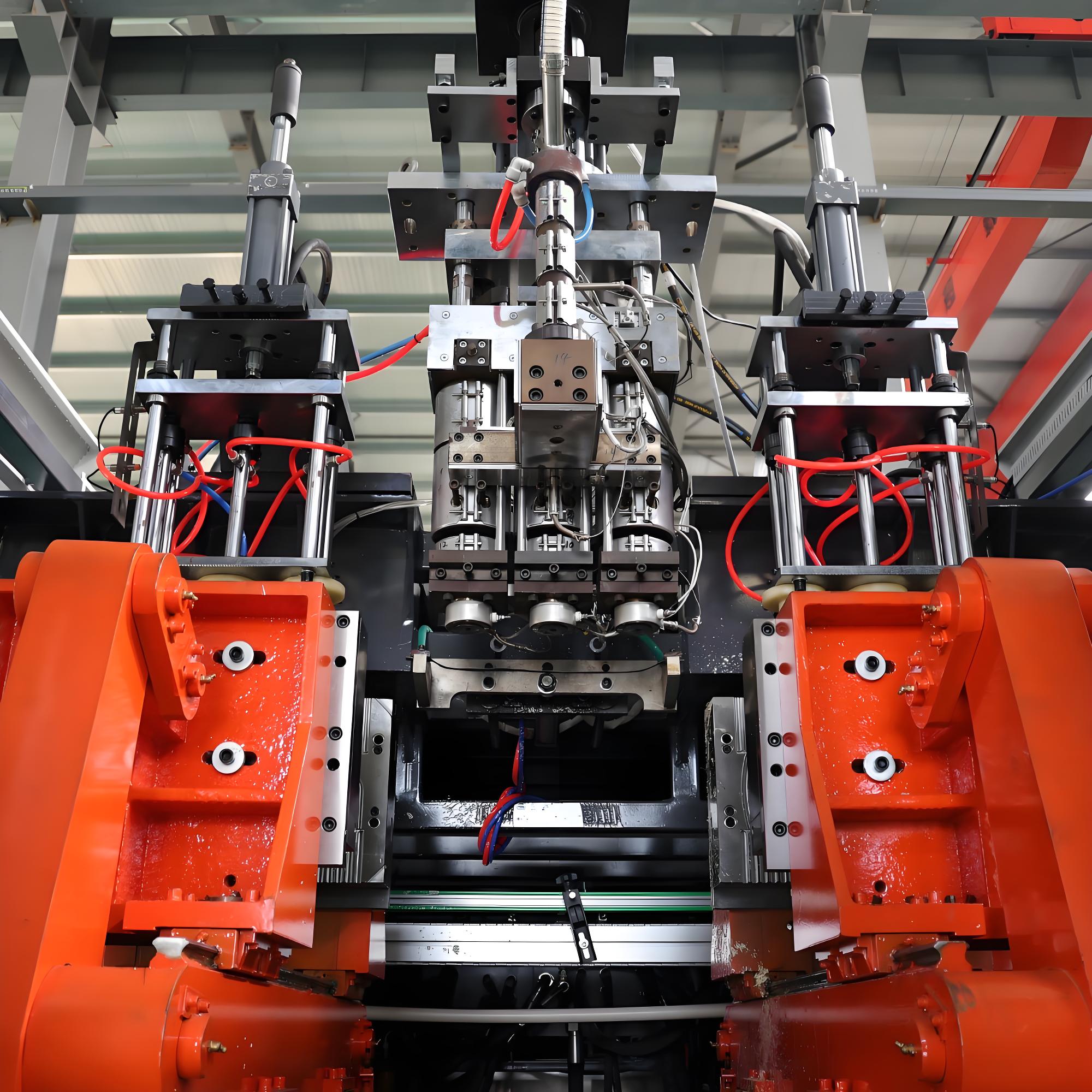
II. Clamping and Locking System
This section is responsible for quickly and accurately closing the mold and providing sufficient clamping force to resist the internal air pressure of the parison during the blowing process, preventing the mold from opening.
- Clamping Unit
- Function: Drives the mold to open and close.
- Types:
- Hydraulic Drive: The most common method, using hydraulic cylinders to move the platens, providing powerful clamping force.
- Electric Drive: Uses servo motors and ball screws to move the platens, offering high precision, fast response, and low energy consumption.
- Core Components:
- Moving Platen: Holds one half of the mold.
- Stationary Platen: Holds the other half of the mold, typically fixed to the extrusion blow molding machine frame.
- Tie Bars: Connect the moving and stationary platens, providing guidance and support for the clamping mechanism and withstanding the clamping force.
- Clamping Cylinder / Servo Motor: Provides the clamping power.
- Clamping Force
- Definition: Refers to the maximum clamping force the system can provide once the mold is fully closed.
- Importance: The clamping force must be sufficiently large to ensure the mold does not separate due to the high internal pressure of the parison during blowing. Insufficient force can lead to flash, deformation, or failure to form. The required clamping force is typically related to the projected area of the product and the blowing pressure.
III. Blowing System
This section is responsible for blowing compressed air into the molten parison, causing it to expand and conform to the mold cavity, forming the final product shape.
- Compressed Air Source
- Function: Provides high-pressure, dry, and clean compressed air.
- Components: Typically includes an air compressor, air receiver tank, air dryer, and filters.
- Blow Pin / Blow Rod
- Function: Precisely introduces compressed air into the interior of the parison.
- Features: Usually installed inside the mold or on the clamping unit. After the mold closes, the blow pin inserts into the bottom or top of the parison before air is blown in.
- Air Circuit Control System
- Function: Controls the pressure, flow rate, and blowing time of the compressed air.
- Core Components: Includes various solenoid valves, pressure regulators, flow control valves, and pressure sensors.
IV. Product Ejection System
This section is responsible for removing the product from the mold after it has cooled and solidified.
- Robot / Take-out Device
- Function: Automatically removes the product from the mold and places it in a designated location (e.g., a conveyor belt).
- Features: An essential component for fully automatic extrusion blow molding machines, its efficiency directly impacts the machine’s overall production cycle. The robot’s movements are typically driven by servo motors or pneumatic cylinders, offering high precision and speed.
V. Control System
This is the “brain” of the extrusion blow molding machine, responsible for coordinating and controlling the actions of all other systems to ensure the accuracy and stability of the entire blow molding process.
- Controller
- Core Component: Usually a Programmable Logic Controller (PLC) or an industrial computer.
- Function: Receives signals from various sensors and sends commands to actuators (e.g., motors, hydraulic cylinders, solenoid valves) based on preset programs (recipes).
- Human-Machine Interface (HMI)
- Function: The platform for operator interaction with the machine.
- Features: Typically a touchscreen, allowing operators to set process parameters (e.g., temperature, pressure, speed, time), monitor the production process, view production data, and access alarm information.
- Sensors
- Function: Real-time monitoring of various extrusion blow molding machine states and process parameters, feeding signals back to the controller.
- Common Types: Temperature sensors, pressure sensors, position sensors, speed sensors, photoelectric sensors, etc.
VI. Auxiliary Systems
While not directly involved in the plasticization and molding process, these systems are crucial for the extrusion blow molding machine’s normal operation and product quality.
- Heating and Cooling System
- Heating: Provides heat to the extruder, die head, and mold to melt the plastic and maintain it at the appropriate processing temperature. Electric heating bands are commonly used.
- Cooling:
- Mold Cooling: Circulates cooling water through channels inside the mold to rapidly cool and solidify the product. Cooling efficiency directly affects the production cycle and product quality.
- Barrel Cooling: Cooling fans or water cooling devices are installed in certain barrel sections (e.g., the feeding zone) to precisely control material temperature and prevent overheating and decomposition.
- Hydraulic Oil Cooling: Required for hydraulically driven extrusion blow molding machines to ensure the hydraulic system operates normally.
- Hydraulic System
- Function: Provides power to the clamping unit, locking mechanism, accumulator (for intermittent machines), etc.
- Core Components: Hydraulic pump, hydraulic cylinders, hydraulic valves, oil tank, oil filter, and cooler.
- Lubrication System
- Function: Lubricates moving parts (e.g., screw, tie bars, guide pillars) to reduce friction and wear, extending extrusion blow molding machine life.
- Safety System
- Function: Protects the safety of operators and equipment.
- Common Devices: Safety doors, safety light curtains, emergency stop buttons, overload protection devices, etc.
An extrusion blow molding machine is a complex system integrating mechanical, electrical, hydraulic, pneumatic, and automated control technologies. Each component is interconnected and interdependent, working together to complete the transformation from plastic pellets to hollow products. Understanding its structure and the function of each part is essential for proper operation, maintenance, and optimization of the production process.
Working Principle
Extrusion Blow Molding is a manufacturing process that transforms thermoplastic polymer melts into hollow products. It involves extruding a molten plastic tube, known as a parison, into a mold cavity, inflating it with compressed air to conform to the mold shape, and then cooling and solidifying it.
The core working principle can be broken down into the following key stages:
I. Material Preparation and Plasticization
- Material Loading: Dry thermoplastic pellets (e.g., HDPE, PP, PVC, PET) are fed into the extruder via a hopper.
- Heating and Melting: The extruder barrel is externally heated by heating bands. As the internal screw rotates, it conveys the pellets forward. During this process, the pellets are heated externally by the barrel and internally by the shear friction generated by the screw, gradually transitioning from a solid state to a homogeneous, viscous molten plastic.
- Compression and Mixing: The screw’s design (typically with a gradually decreasing pitch and depth) applies significant compression and shear forces to the molten plastic. This ensures thorough mixing and uniform plasticization, resulting in a bubble-free and impurity-free melt.
II. Parison Extrusion
- Melt Conveying: The plasticized melt is continuously or intermittently conveyed by the screw to the die head.
- Parison Formation: The melt passes through specialized flow channels and a die orifice within the die head, emerging as a tubular plastic shape of a specific wall thickness and diameter, known as a parison.
- Wall Thickness Control: For high-precision applications, the die head incorporates a Wall Thickness Control System (WTC). This system typically uses a servo-motor driven adjustable mandrel or valve pin to dynamically adjust the parison’s wall thickness profile according to a preset program. This compensates for parison sagging under gravity, ensuring uniform wall thickness in the final product.
III. Mold Closing and Parison Pinching
- Mold Positioning: When the parison reaches the predetermined length, the control system signals the molds, located on either side of the parison, to close rapidly.
- Pinching and Sealing: The mold cavity defines the final product’s shape. The mold edges are specifically shaped to firmly pinch the top and bottom of the parison upon closing. This action simultaneously performs several functions:
- Cutting the Parison: Separates the parison inside the mold from the portion still being extruded.
- Sealing the Bottom: Fuses and seals the bottom of the parison, creating an inflatable “bag”.
- Securing the Parison: Prevents the parison from moving during the blowing process.
IV. Blowing and Cooling
- Air Injection: Once the mold is fully closed, one or more blow pins rapidly insert into the top (or bottom) of the parison. High-pressure, dry compressed air is then introduced into the parison.
- Inflation and Shaping: The pressure from the compressed air causes the soft, molten parison to inflate like a balloon, pressing it tightly against the inner walls of the mold cavity, thus replicating the mold’s shape.
- Cooling and Solidification: The mold contains internal cooling water channels. As the parison inflates, cooling water circulates, rapidly removing heat from the plastic via conduction. Upon contact with the cold mold surface, the plastic melt cools quickly, transitioning from a viscous flow state to a highly elastic state, and finally solidifying into a glassy or crystalline state, permanently fixing the mold’s shape.
V. Mold Opening and Product Ejection
- Mold Opening: Once the product has cooled sufficiently to achieve the required hardness and strength, the mold opens.
- Product Removal: The product is ejected from the mold. In fully automaticextrusion blow molding machines, this is done automatically by a robot or take-out device; in semi-automatic machines, manual assistance may be required.
- Post-Processing: The ejected product typically has flash (excess plastic) from the mold clamping area, which is removed in subsequent trimming operations to yield the final product.
The entire extrusion blow molding process can be summarized as: Plastic Pellets → (Extruder) → Melting & Plasticization → (Die Head) → Parison Formation → (Mold) → Mold Closing & Pinching → (Blow Pin) → Compressed Air Introduction → Inflation & Shaping → (Cooling Water) → Cooling & Solidification → Mold Opening → Product Ejection.
This is a cyclical process. By precisely controlling the temperature, pressure, speed, and time of each stage, hollow plastic products of various sizes, shapes, and wall thicknesses can be produced.
Applications
Extrusion Blow Molding Machines are widely used in modern manufacturing due to their robust molding capabilities and broad material compatibility. They can produce hollow plastic products ranging in size from small bottles of a few milliliters to large storage tanks of several thousand liters.
Their main application areas can be broadly categorized based on product size, shape, and intended use:
I. Small-Sized Hollow Products
This is the most common application area for extrusion blow molding machines, primarily focused on manufacturing various packaging containers.
- Beverage & Food Packaging
- Applications: Mineral water bottles, beverage bottles (e.g., cola, juice), cooking oil bottles, condiment bottles (e.g., soy sauce, vinegar, ketchup), milk bottles, yogurt bottles, food jars (e.g., for nuts, cookies), etc.
- Materials: Primarily HDPE (High-Density Polyethylene), PP (Polypropylene), and PET (Polyethylene Terephthalate).
- Characteristics: High production volumes, high automation levels, and strict requirements for product wall thickness uniformity and appearance.
- Daily Chemical & Pharmaceutical Packaging
- Applications: Bottles for shampoo, body wash, conditioner, laundry detergent, dish soap, etc.; pharmaceutical bottles (e.g., syrup bottles, dropper bottles), medicine containers, spray bottles, etc.
- Materials: HDPE, PP, PVC (Polyvinyl Chloride).
- Characteristics: Emphasis on product sealability, safety, and aesthetics. Some pharmaceutical packaging has strict requirements for cleanliness.
- Small Industrial & Household Containers
- Applications: Engine oil bottles, lubricant containers, glue pots, paint cans, small-capacity chemical reagent bottles, hand sanitizer bottles, disinfectant bottles, etc.
- Materials: HDPE, PP, PVC, ABS (Acrylonitrile Butadiene Styrene).
- Characteristics: Specific requirements for chemical resistance and oil resistance of materials, depending on the contents.
II. Medium-Sized Industrial & Chemical Containers
These products are larger in size and capacity, mainly used for industrial production and the storage and transportation of chemical raw materials.
- Chemical Drums
- Applications: Used for storing and transporting various liquid chemical raw materials, solvents, coatings, inks, etc. Common sizes include 20L, 30L, 50L, 120L, 200L, etc.
- Materials: Primarily HDPE, due to its excellent chemical resistance and impact resistance.
- Characteristics: Extremely high requirements for product strength, rigidity, corrosion resistance, and sealability. Often black for UV protection or specific colors to differentiate contents.

- IBC Totes (Intermediate Bulk Containers)
- Applications: A type of bulk container, typically consisting of an HDPE inner container and a metal frame, with a capacity generally of 1000L. Widely used for the storage and transportation of bulk liquid materials in the chemical, food, pharmaceutical, and other industries.
- Materials: Inner container is HDPE.
- Characteristics: Robust structure, stackable, easy for mechanical handling and transportation, an important tool in modern logistics.
- Automotive Components
- Applications: Automotive fuel tanks, air ducts, coolant reservoirs, bumpers (some large bumpers), interior parts, etc.
- Materials: HDPE (fuel tanks), PP (air ducts, coolant reservoirs), ABS or PC/ABS alloys (interior parts).
- Characteristics: High requirements for product dimensional accuracy, structural strength, weather resistance, and lightweighting.
III. Large-Sized Hollow Products
These products are very large and typically require large or extra-large extrusion blow molding machines for production.
- Large Storage Tanks
- Applications: Used for storing water, chemical raw materials, petroleum products, etc. Capacities can reach several cubic meters or more.
- Materials: HDPE.
- Characteristics: Strong corrosion resistance, long service life, and easy installation.
- Transportation & Municipal Facilities
- Applications: Plastic road barriers, traffic bollards, traffic cones, trash bins, large pipes (e.g., corrugated pipes), etc.
- Materials: HDPE, PP.
- Characteristics: Lightweight, impact-resistant, weather-resistant, and easy to handle and install.
- Plastic Furniture & Toys
- Applications: Plastic chairs, tables, large toys (e.g., slides, amusement park components), plastic boats, etc.
- Materials: HDPE, PP.
- Characteristics: Bright colors, diverse shapes, durable, and easy to clean.
IV. Specialized Applications
- Medical Industry
- Applications: Housings for certain medical devices, casings for artificial lungs (oxygenators), etc.
- Materials: PVC, PP, PC (Polycarbonate).
- Characteristics: Strict requirements for material biocompatibility, cleanliness, and precision.
- Agricultural Sector
- Applications: Pesticide bottles, large fertilizer bags, agricultural sprayers, small agricultural machinery parts, etc.
- Materials: HDPE, PP.
- Characteristics: Corrosion resistance and weather resistance.
The applications of extrusion blow molding machines cover almost every aspect of our daily lives and industrial production. Their core advantage lies in their ability to efficiently and economically produce hollow plastic products of various sizes, shapes, and functions using a wide range of thermoplastic raw materials. With continuous technological advancements, such as multi-layer co-extrusion, precise wall thickness control, and all-electric drives, the application range of extrusion blow molding machines is constantly expanding, meeting the demands of increasingly high-end and complex markets.
Comparison of Extrusion Blow Molding Machines with Other Blow Molding Technologies
In the field of plastic blow molding, there are three main technological routes: Extrusion Blow Molding (EBM), Injection Blow Molding (IBM), and Injection Stretch Blow Molding (ISBM). Among them, ISBM is an important branch of IBM, primarily used for manufacturing PET bottles.
Below is a detailed comparison between them:
I. Comparison of Core Process Principles
| Process Type | Core Principle |
|---|---|
| Extrusion Blow Molding (EBM) | 1. Parison Extrusion: Plastic melt is continuously or intermittently extruded through an extruder to form a tubular parison. 2. Mold Closing & Pinching: The mold closes, pinching both ends of the parison. 3. Blowing: Compressed air is introduced from one end (usually the bottom) of the mold, causing the parison to inflate and conform to the mold cavity. 4. Cooling & Solidification: Cooling water circulates inside the mold to cool and solidify the plastic. 5. Mold Opening & Ejection: The mold opens, and the product is ejected. |
| Injection Blow Molding (IBM) | 1. Preform Injection: Plastic melt is injected by an injection molding machine into a preform mold to form a preform with a threaded neck finish. 2. Mold Transfer: The preform mold opens, and the preform is transferred to a blow mold. 3. Blowing: A blow rod extends into the preform, and compressed air is introduced to inflate it against the blow mold cavity. 4. Cooling & Ejection: After cooling, the mold opens, and the product is ejected. |
| Injection Stretch Blow Molding (ISBM) | 1. Preform Injection: Same as the first step of IBM, a threaded preform is injected. 2. Heating & Conditioning: The preform is reheated to a temperature near its glass transition temperature (“reheating”). 3. Stretching & Blowing: In the blow mold, a stretch rod first stretches the preform axially, followed immediately by radial stretching and inflation with compressed air. 4. Cooling & Ejection: After cooling, the mold opens, and the product is ejected. |
II. Comparison of Key Features, Advantages, and Disadvantages
| Comparison Dimension | Extrusion Blow Molding (EBM) | Injection Blow Molding (IBM) | Injection Stretch Blow Molding (ISBM) |
|---|---|---|---|
| Product Shape | Can produce hollow products with complex, irregular shapes, handles, or inserts.Neck finish usually requires secondary processing. | Mainly produces bottles with symmetrical bodies and relatively simple shapes. Neck finish is formed during the preform stage, no secondary processing needed. | Mainly produces bottles with symmetrical bodies, high transparency, and high strength (e.g., PET bottles). Neck finish is formed during the preform stage. |
| Material Suitability | Wide range of materials, including HDPE, PP, PVC, ABS, PC, EVA, etc. | Mainly suitable for PP, HDPE, PET, PS, etc. | Mainly suitable for PET, also for PP, PBT, etc. |
| Production Efficiency | Higher efficiency for large, complex products. Lower efficiency than ISBM for small bottles. | Longer production cycle, relatively lower efficiency. | Very high production efficiency, ideal for large-scale, standardized bottle production (e.g., beverage bottles). |
| Product Quality | Advantages: Suitable for large, thick-walled, complex-shaped products. Disadvantages: Relatively poor wall thickness uniformity (affected by parison sagging), average neck finish quality, requires post-processing. | Advantages: High neck finish quality, good dimensional accuracy, no flash. Disadvantages: Limited bottle body shapes, cannot produce complex structures. | Advantages: Products have excellent transparency, high strength, uniform wall thickness, good lightweighting effect, and high neck finish quality. Disadvantages: Extremely high requirements for material and process control, limited product shapes. |
| Equipment & Mold Cost | Relatively simple equipment structure, lower cost. Lower mold cost. | Equipment requires two systems (injection and blow molding), complex structure, higher cost. High mold cost (preform mold + blow mold). | Most complex equipment (injection + heating + stretching + blow molding), highest cost. Highest mold cost. |
| Applications | Large chemical drums (200L Drum) IBC Totes Automotive fuel tanks, air ducts Large toys, furniture Small bottles (e.g., pesticide bottles, engine oil bottles) | Pharmaceutical bottles, cosmetic bottles. Some small food packaging bottles | Carbonated beverage bottles, Mineral water bottles, Cooking oil bottles, High-end cosmetic bottles |
Summary and Selection Recommendations
- Choose Extrusion Blow Molding (EBM) if you need to:
- Produce large, thick-walled, complex-shaped hollow products.
- Use a wide variety of plastic materials.
- Keep initial investment in equipment and molds low.
- Typical applications: Chemical drums, automotive components, large toys.
- Choose Injection Blow Molding (IBM) if you need to:
- Produce small, high-precision, high surface quality bottles with no need for neck finish post-processing.
- Have extremely high hygiene requirements for the product (e.g., pharmaceuticals, food).
- Typical applications: Small-capacity pharmaceutical bottles, high-end cosmetic bottles.
- Choose Injection Stretch Blow Molding (ISBM) if you need to:
- Mass-produce highly transparent, high-strength, lightweight PET bottles.
- Achieve excellent wall thickness uniformity and surface finish for your products.
- Typical applications: Beverage bottles, mineral water bottles, cooking oil bottles.
In summary, extrusion blow molding machines have irreplaceable advantages in producing large, complex hollow products due to their flexibility, wide material compatibility, and relatively low cost. Injection blow molding and injection stretch blow molding are more competitive in producing small, high-precision, standardized bottle products.
The Evolutionary History of Extrusion Blow Molding Machines
The history of the Extrusion Blow Molding (EBM) machine can be traced back to ancient glassblowing techniques. It has undergone a technological evolution from manual to automated processes, and from simplicity to complexity, roughly divided into the following key stages:
I. Early Exploration Stage (1st Century BC – 1930s)
- Technological Origins: The fundamental principle of extrusion blow molding traces its roots to the glassblowing techniques developed in the Middle East around the 1st century BC, a technology that persisted in Europe for nearly two millennia.
- Initial Attempts: In the 18th century, experimental blow molding using natural resins began in Europe, but industrial production was not feasible due to material limitations.
- Sprouting of Modern Technology: With the advent of synthetic plastics in the 1930s, modern blow molding technology began to take shape:
- 1935: Enoch Ferngren and William Kopitke developed a process for blow molding articles.
- 1936: They transferred this method to the Hartford Empire Company, which then established the PLAX Development Company. The same year saw the birth of the first dedicated blow molding machine for hollow products.
- 1938: PLAX introduced the first commercial blow molding machine, marking a significant milestone for the industry.
- 1939: The first large-scale production of plastic bottles, primarily using cellulose acetate, was realized in the United States.
II. Technological Foundation and Initial Development Stage (1940s – 1950s)
- Material Breakthrough: In the mid-1940s, the British company ICI developed Low-Density Polyethylene (LDPE). Its unbreakable nature was incomparable to glass, providing a crucial material foundation for the advancement of blow molding technology.
- WWII Impetus: During World War II, the blow molding process began to be used for producing small LDPE bottles to meet the packaging needs of military supplies.
- Key Patents and Equipment:
- 1946: American engineers R. Bott and G. J. Crawford at Illinois Tool Works developed the first commercial extrusion blow molding equipment.
- 1949: German brothers Norbmt and Reinold Hagen invented a method and apparatus for producing thermoplastic bottles, obtaining a German patent in May 1950, which propelled the development of extrusion blow molding technology in Europe.
- 1950: Elmer Mill invented the continuous extrusion rotary blow molding machine patent, which was adopted by Continental Can, significantly increasing production efficiency.
- 1953: German company Battenfeld introduced the world’s first screw-type extrusion blow molding machine. This innovation increased extrusion efficiency by 300% and reduced product wall thickness variation from ±15% to ±8%, creating conditions for large-scale industrial production.
- Material and Application Expansion: In the late 1950s, High-Density Polyethylene (HDPE) became commercially available, expanding the volume of blow-molded products from milliliters to thousands of liters and rapidly broadening the scope of applications.
III. Technological Maturity and Rapid Expansion Stage (1960s – 1980s)
- Material Diversification: Various thermoplastics such as Polypropylene (PP), Polyvinyl Chloride (PVC), ABS, and PC began to be used in extrusion blow molding, greatly expanding the product range.
- Equipment Technological Advances:
- Development of Multi-Layer Co-Extrusion Technology: Progressed from two-layer to six-layer co-extrusion. In particular, multi-layer co-extrusion technology for plastic fuel tanks opened up new application areas.
- Improvement of Wall Thickness Control Technology: Static flexible die rings and local wall thickness control technology enabled uniform wall thickness control for complex containers.
- Increased Automation: Introduction of hydraulic systems and simple electronic control systems improved production stability and precision.
- Application Field Expansion:
- 1960s: Production of large industrial containers such as 200L chemical drums and IBC totes began.
- 1970s: Computer control systems were introduced, enabling precise regulation of process parameters and further enhancing product quality and consistency.
- 1980s: 20-liter Polycarbonate (PC) water bottles started to replace bulky glass bottles, and multi-layer blow molding technology advanced further.
IV. Technological Innovation and Intelligentization Stage (1990s – Early 21st Century)
- Precision Control Technology: PLC control systems, servo motors, and sensor technology were widely adopted, enabling precise monitoring and automatic adjustment of the entire process, including extrusion, blowing, and cooling.
- Development of Special Molding Technologies:
- 3D Blow Molding: Used for manufacturing complex automotive pipelines and irregular hollow products.
- Maturation of Stretch Blow Molding (ISBM) Technology: Primarily used for the mass production of PET bottles, complementing extrusion blow molding.
- Co-Extrusion Technology Breakthrough: Advanced to over 7 layers, achieving stable co-extrusion of barrier materials like EVOH and PA, applied in food packaging and fuel tank sectors.
- Energy Saving and Environmental Protection Technologies:
- High-efficiency screw designs reduced energy consumption.
- Waste heat recovery systems were applied.
- Improved compatibility with biodegradable materials.
- Large-Scale and Customization: Equipment capable of producing extra-large hollow products with volumes of several thousand liters, while also meeting the demands of small-batch customized production.
V. Contemporary Development and Future Trends (2010s – Present)
- Intelligent Upgrading:
- Application of Industry 4.0 Technologies: Internet of Things (IoT), big data analytics, and Artificial Intelligence (AI) are used for predictive maintenance and process optimization.
- Digital Twin Technology: Creating virtual production environments for process simulation and parameter optimization.
- Remote Monitoring and Diagnostics: Reducing maintenance costs and improving equipment utilization.
- Material Innovation and Sustainable Development:
- Improved compatibility with bio-based plastics and recycled plastics, responding to global environmental trends.
- Lightweight Design: Reducing plastic usage and carbon emissions through optimized wall thickness distribution and material selection.
- High-Efficiency Production Technologies:
- High-Speed Extrusion Systems: Increasing production efficiency to meet mass production demands.
- Multi-Head Technology: A single extrusion blow molding machine can produce multiple products simultaneously, boosting productivity.
- Further Expansion of Application Areas:
- Medical Field: Production of high-precision, high-hygiene standard medical containers.
- New Energy Vehicles: Application of lightweight plastic components (e.g., battery casings, cooling systems).
- Smart Home: Production of various irregular hollow structural components.
VI. Summary Table of Key Milestones in EBM Development
| Time | Key Event | Technological Impact |
|---|---|---|
| 1938 | Introduction of the first commercial blow molding machine | Marked the beginning of the modern blow molding industry |
| 1946 | Development of the first commercial extrusion blow molding equipment | Established the extrusion blow molding technical route |
| 1953 | Birth of the first screw-type extrusion blow molding machine | Significantly improved efficiency and wall thickness uniformity |
| 1950s-1960s | Commercialization of HDPE | Expanded product volume to thousands of liters |
| 1970s | Introduction of computer control systems | Enabled precise regulation of process parameters |
| 1980s-1990s | Development of multi-layer co-extrusion technology | Expanded applications for high-barrier products |
| Early 21st Century | Popularization of intelligent control systems | Enhanced product quality stability |
| 2010s-Present | Application of Industry 4.0 and sustainable technologies | Driving the industry towards higher efficiency and environmental friendliness |
The development history of extrusion blow molding machines is a microcosm of the synergistic progress of materials science, mechanical engineering, and control technology. From early imitations of glassblowing to today’s highly intelligent production systems, extrusion blow molding machines maintain an irreplaceable position in the production of large, complex hollow products due to their flexibility, wide material compatibility, and relatively low cost. They continue to evolve towards greater efficiency, environmental friendliness, and intelligence to meet changing market demands and global sustainability goals.
Major Brands and Manufacturers
The Extrusion Blow Molding (EBM) machine market presents a landscape where international giants dominate the high-end market, while Chinese brands are rising rapidly. Below is a categorized introduction of global renowned brands and major Chinese manufacturers, covering their technical characteristics, market positioning, and core advantages:
I. Global Renowned Extrusion Blow Molding Machine Brands (International Giants)
| Brand | Country | Founded | Core Advantages | Representative Products | Applications |
|---|---|---|---|---|---|
| Kautex | Germany | 1935 | Leader in the automotive industry, all-electric technology, expert in multi-layer co-extrusion | KBB Series (All-Electric), KLS Series (Long Stroke), KEB Series (Single-Station) | Automotive fuel tanks, industrial packaging, special components |
| Bekum | Germany | 1952 | Pioneer in global EBM technology, high stability, modular design | H-1000, BM Series, EBlow Series | Medical packaging, food containers, industrial drums |
| Graham Engineering | USA | 1960 | Expert in large containers, high-speed production lines, precision control | Graham Wheel, Graham Single Station | IBC Totes, large chemical containers, automotive components |
| Uniloy Milacron | USA | 1940s | Wide material compatibility, high-efficiency production systems, customized solutions | UMS Series, Maxima Series | Cosmetic packaging, pharmaceutical containers, small industrial parts |
| Sidel | Switzerland (a Tetra Laval Group company) | 1965 | Leader in beverage packaging, complete line solutions | SBO Universal, SBL Series | Plastic bottles, beverage packaging, food containers |
| Krones | Germany | 1951 | Packaging line integrator, high level of intelligence | Krones Blow Molding | Beverage, food, chemical packaging |
| Battenfeld-Cincinnati | Germany/USA | 1953 | Leading screw technology, high efficiency, high precision wall thickness control | BC Series, TM Series | Industrial containers, automotive components, large hollow products |
| SMF | Germany | 1948 | Expert in medical-grade products, cleanroom solutions | SMF Medical Line | Medical bottles, pharmaceutical packaging, high-cleanliness containers |
II. Major Chinese Extrusion Blow Molding Machine Manufacturers (Leading Local Enterprises)
| Brand | Location | Founded | Core Advantages | Representative Products | Market Coverage |
|---|---|---|---|---|---|
| Guangdong Jinming Precision Machinery (JINMING) | Shantou, Guangdong | 1987 | Leading multi-layer co-extrusion technology, high intelligence | Jwell Series, JM Series | Food packaging, medical containers, automotive components |
| Leshan Machinery | Foshan, Guangdong | 1995 | Top 3 EBM manufacturer in China, high cost-performance ratio, comprehensive service network | LS Series, LSP Series (Multi-layer) | Daily chemical packaging, food containers, industrial drums |
| Suzhou Tongda Machinery (TONGDA) | Suzhou, Jiangsu | 1999 | Sales network in over 120 countries, expert in HDPE containers | TD Series, TDM Series (Multi-layer) | Daily chemical bottles, engine oil bottles, chemical drums |
| Shandong Tongjia Machinery (TONGJIA) | Jining, Shandong | 1993 | Expert in large hollow products, outstanding energy-saving technology | TJ Series, TJM Series | 200L chemical drums, IBC Totes, automotive components |
| Guangzhou Dylon Machinery (DYLON) | Guangzhou, Guangdong | 1998 | Complete line solutions for beverage packaging, intelligent production lines | DYLON Blow Molding | Beverage bottles, food packaging, daily chemical containers |
| Zoya Machinery (ZOYA) | Hangzhou, Zhejiang | 1992 | Expert in medical-grade products, clean production systems | ZY Series, ZYM Series | Medical containers, pharmaceutical packaging, high-cleanliness products |
| Zhangjiagang Apollo Machinery | Zhangjiagang, Jiangsu | 2007 | Full product range coverage (5ml-5000L), annual production capacity of 100 units | ABLD Series, ABLB Series, Full electric | Industrial packaging, daily necessities, food containers |
| Jiangsu Useon Technology (useon) | Nanjing, Jiangsu | 2006 | National High-Tech Enterprise, expert in polymer material extrusion | Useon Series, USE Series | Special plastic containers, functional packaging |

III. Brand Classification and Selection Reference
1. Classification by Technical Positioning
| Technology Level | Representative Brands | Features | Applicable Scenarios |
|---|---|---|---|
| High-End All-Electric | Kautex, Bekum, Sidel | High precision, low energy consumption, high stability | Automotive components, medical containers, high-end packaging |
| Mid-Range Hydraulic/Servo Hybrid | Battenfeld-Cincinnati, Uniloy Milacron | High cost-performance ratio, moderate efficiency | Industrial packaging, food containers, daily chemicals |
| Economical Hydraulic | Leshan, Tongda, Tongjia | Affordable price, simple maintenance | Small and medium-sized enterprises, mass production of standard products |
2. Classification by Application Field
| Application Field | Recommended Brands | Technical Requirements |
|---|---|---|
| Automotive Industry | Kautex, Graham, Battenfeld | Multi-layer co-extrusion, long stroke, chemical resistance |
| Medical Packaging | SMF, Bekum, Jinming Precision Machinery | High cleanliness, precision control, material compatibility |
| Food & Beverage | Sidel, Krones, Dylon | High hygiene standards, complete line integration, high-speed production |
| Industrial Containers | Graham, Tongjia, Apollo | Large-scale, high strength, corrosion resistance |
| Daily Chemical Packaging | Leshan, Uniloy, Bekum | Exquisite appearance, uniform wall thickness, multi-material compatibility |
IV. Industry Characteristics and Development Trends
- Accelerated Technology Integration: Competition between international brands and Chinese enterprises in multi-layer co-extrusion, intelligent control, and energy-saving technology is intensifying, with the technical gap between Chinese brands rapidly narrowing.
- Complete Line Solutions Becoming Mainstream: Transformation from single-machine sales to “blowing + filling + packaging” complete line delivery, where international brands like Sidel and Krones have obvious advantages.
- Rise of Green Manufacturing: All-electric models (e.g., Kautex KBB Series) reduce energy consumption by more than 30%, and compatibility with bio-based materials has become a new competitive point.
- Growing Demand for Customization: Automotive lightweighting and medical high-endization drive the development of special models, such as Kautex’s long-stroke models adapted for new energy vehicle component production.
V. Selection Recommendations
- High-End Applications: Priority should be given to international brands such as Kautex and Bekum, which have mature technology and high stability, suitable for scenarios with strict product quality requirements.
- Mid-Range Market: Consider Battenfeld-Cincinnati or leading Chinese brands (Jinming, Leshan) for their high cost-performance ratio and fast service response.
- Mass Production of Standard Products: Choose mainstream Chinese brands (Apollo, Tongjia) for their significant cost advantages, suitable for investment by small and medium-sized enterprises.
- Special Requirements: For medical-grade or automotive-specific needs, it is recommended to choose professional brands in the corresponding fields (SMF, Graham) to avoid technical risks.
Extrusion Blow Molding Machine Prices by Type (USD)
Below is a comprehensive price guide for different types of extrusion blow molding machines (EBM), organized by technology, size, application, and brand origin, with USD as the base currency . Prices reflect new equipment as of Q4 2025 and may vary by configuration, customization, and regional factors .
I. Price by Technology Type
| Technology | Price Range (USD) | Representative Brands | Key Features | Applications |
|---|---|---|---|---|
| Fully Electric | $145,000–$800,000+ | Kautex, Bekum, Sidel, Apollo | High precision, energy saving (30%+), fast cycle times, low noise Kautex | Automotive fuel tanks, medical containers, high-end packaging Kautex |
| Servo-Hydraulic Hybrid | $60,000–$350,000 | Battenfeld-Cincinnati, Uniloy, Apollo | Balanced performance, cost-effective, good control accuracy | Industrial packaging, food containers, daily chemicals |
| Economical Hydraulic | $8,500–$55,000 | Leshan, Apollo, Tongjia | Affordable, simple maintenance, reliable operation | Small/medium enterprises, standard products, low-budget projects |
| Accumulator Head | $120,000–$500,000 | Graham, Kautex, Tongjia | For large hollow products, high output, thick wall capability | 200L drums, IBC totes, large industrial containers |
| Continuous Extrusion | $7,800–$180,000 | Bekum, SMF, Apollo | Simple structure, continuous production, suitable for small-to-medium products | Small bottles, daily chemical containers, toys |
II. Price by Product Size/Capacity
| Product Size | Price Range (USD) | Machine Type | Typical Applications |
|---|---|---|---|
| Miniature (≤500ml) | $7,800–$25,000 | Single-station, small screw (30–50mm) | Cosmetic bottles, small medical containers, sample bottles |
| Small (0.5–5L) | $18,000–$60,000 | Single/double station, screw 50–75mm | Jerry cans, detergent bottles, engine oil bottles |
| Medium (5–50L) | $35,000–$150,000 | Double station, accumulator head, screw 75–90mm | 20L buckets, chemical containers, large packaging |
| Large (50–200L) | $80,000–$280,000 | Heavy-duty accumulator, multi-station, screw 90–120mm | 200L industrial drums, large plastic tanks |
| Extra Large (≥1000L/IBC Totes) | $198,000–$450,000+ | Specialized accumulator, large stroke, screw 120–180mm | 1000L IBC tanks, large chemical storage containers |
| Automotive Components | $250,000–$800,000+ | Long-stroke, multi-layer co-extrusion, all-electric Kautex | Fuel tanks, air ducts, battery housings Kautex |
III. Price by Number of Layers (Co-extrusion)
| Layers | Price Range (USD) | Key Features | Applications |
|---|---|---|---|
| Single Layer | $7,800–$180,000 | Basic model, simple structure, low cost | Standard packaging, non-specialty products |
| 2–3 Layers | $25,000–$220,000 | Enhanced barrier properties, improved strength | Food packaging, chemical containers, oil bottles |
| 4–5 Layers | $62,000–$350,000 | High barrier, multi-material compatibility, EVOH integration | Medical packaging, fuel tanks, high-end food containers |
| 6+ Layers | $200,000–$600,000+ | Advanced technology, complex control systems | Automotive fuel systems, specialty chemical packaging |
IV. Price Comparison: International vs. Chinese Brands
| Brand Origin | Price Range (USD) | Quality/Performance | Service | Lead Time |
|---|---|---|---|---|
| International Premium (Kautex, Bekum, Sidel) | $250,000–$800,000+ | Top-tier, high precision, long lifespan (15–20 years) Kautex | Global support, advanced training Kautex | 16–24 weeks Kautex |
| International Mid-Range (Uniloy, Battenfeld) | $120,000–$350,000 | Good quality, reliable performance Kautex | Regional support centers Kautex | 12–16 weeks Kautex |
| Chinese Premium (Jinming, Jwell, Leshan) | $60,000–$280,000 | Near-international quality, high cost-performance | Local support, fast response | 8–12 weeks |
| Chinese Mid-Range (Tongda, Tongjia, Dylon) | $35,000–$150,000 | Reliable, cost-effective, suitable for standard applications | Domestic support, export service | 6–8 weeks |
| Chinese Economic (Local manufacturers) | $7,800–$45,000 | Basic functionality, simple design | Limited support, basic training | 4–6 weeks |
V. Special Application Machines
| Application | Price Range (USD) | Key Requirements | Recommended Brands |
|---|---|---|---|
| Medical Grade | $80,000–$350,000 | Cleanroom compatibility, precision control, material purity Kautex | SMF, Bekum, Jinming Kautex |
| Food & Beverage | $50,000–$220,000 | High hygiene standards, fast cycle times, easy cleaning Kautex | Sidel, Krones, Dylon Kautex |
| IBC Tote Production | $198,000–$450,000 | Large accumulator, high clamping force, multi-layer capability | Graham, Tongjia, Kautex |
| Automotive Fuel Tanks | $300,000–$800,000+ | 5–7 layer co-extrusion, long stroke, high precision Kautex | Kautex, Graham, Battenfeld Kautex |
| 200L Drum Production | $80,000–$220,000 | Accumulator head, high output, stable wall thickness | Tongjia, Graham, Uniloy |
VI. Price Influencing Factors
- Technology Level: All-electric extrusion blow molding machines cost 30–50% more than hydraulic equivalents but save 30%+ energy over time
- Configuration: Additional features like automatic deflashing, in-mold labeling, and robotic handling add 15–40% to the base price Kautex
- Customization: Special requirements for material compatibility, product shape, or production speed increase costs by 20–50% Kautex
- Brand & Origin: International premium brands cost 2–3x more than Chinese equivalents for similar specifications
- After-sales Service: Extended warranties and global service packages add 5–15% to the price Kautex
VII. Price Summary Table
| Machine Category | Low End (USD) | Mid Range (USD) | High End (USD) | Typical Payback Period |
|---|---|---|---|---|
| Economic Hydraulic | 7,800 | 20,000 | 55,000 | 1–2 years |
| Servo-Hydraulic | 60,000 | 150,000 | 350,000 | 2–3 years |
| All-Electric | 145,000 | 350,000 | 800,000+ | 3–5 years |
| Accumulator Head | 120,000 | 250,000 | 500,000+ | 2–4 years |
| Multi-layer Co-extrusion | 25,000 | 180,000 | 600,000+ | 3–5 years |
Note: Prices are FOB factory prices and do not include shipping, installation, training, or customs duties . Used extrusion blow molding machines typically cost 30–60% less than new ones, depending on age and condition .
Troubleshooting Guide
This guide details common faults, their potential causes, and corresponding solutions encountered in the daily operation of Extrusion Blow Molding (EBM) machines, organized by production stage and fault manifestation for clarity and practicality.
I. Material and Plasticization System Issues
Problems in this category typically stem from the raw material itself or the plasticization process within the extruder, directly impacting parison quality.
| Symptom | Possible Causes | Solutions |
|---|---|---|
| 1. Bubbles, Silver Streaks, or Haze in Products | Insufficiently dried material containing moisture. Material staying in the hopper for too long, absorbing moisture. Extrusion temperature too high, causing material degradation. Worn screw or barrel leading to poor plasticization and melt fracture. Volatile impurities in the material or excessive regrind ratio. | Enhance Drying: Check and increase the temperature and duration of the hopper dryer to ensure material moisture content is below 0.02% (varies by material). Inspect Material: Use fresh material, reduce or eliminate regrind, and check for contamination. Adjust Temperature: Slightly lower the temperature in each extruder zone, especially the die head and rear barrel sections. Check Equipment: Inspect the screw and barrel for wear, repair or replace if necessary. Check for clogged screens. |
| 2. Rough Parison Surface, Burned Particles, or Black Spots | Extrusion temperature too high, causing material overheating and degradation. Material buildup in the die head or barrel, carbonized by prolonged high temperatures. Contamination or mixing of different plastic types in the material. Screw speed too fast, generating excessive shear heat. | Adjust Temperature: Lower the extrusion temperature and optimize the temperature profile. Clean Equipment: Thoroughly clean the die head, screw, and barrel to remove buildup. Use a dedicated purging compound if necessary. Inspect Material: Ensure material purity and absence of contaminants. Adjust Process: Slightly reduce screw speed and increase back pressure (if applicable). |
| 3. Uneven Parison Wall Thickness | Uneven temperature distribution in the die head. Worn or improperly adjusted die orifice or mandrel. Incorrect parameter settings or malfunction of the Wall Thickness Control (WTC) system. Severe parison sagging (for large products). | Check Temperature: Verify and calibrate the temperature of each heating zone in the die head for uniformity. Inspect Die Head: Disassemble and check the die orifice and mandrel for wear, adjusting concentricity. Calibrate WTC: Recalibrate the Wall Thickness Control system and optimize the thickness profile settings. Optimize Process: For large products, slightly increase melt temperature to reduce viscosity or use an accumulator head. |
| 4. Unstable Parison Extrusion (Fluctuating Diameter) | Uneven material feeding (hopper bridging). Unstable screw speed. Hydraulic system pressure fluctuations (for hydraulically driven screws). Clogged screens causing unstable melt pressure. | Improve Feeding: Inspect the hopper to ensure smooth material flow; consider adding a vibratory feeder or agitator. Check Drive: Inspect the screw drive motor and frequency converter for stable speed. Check Hydraulic System: Inspect the hydraulic pump, relief valves, etc., for stable pressure. Replace Screens: Regularly replace the screens at the extruder front. |
II. Clamping and Blowing System Issues
Problems in this category primarily affect product shaping and dimensional accuracy.
| Symptom | Possible Causes | Solutions |
|---|---|---|
| 1. Mold Fails to Close Completely or Insufficient Clamping Force | Clamping force set too low. Foreign objects inside the mold. Misaligned parison, pinched by the mold. Malfunction of the clamping unit (e.g., hydraulic cylinder, servo motor). Unbalanced tie bars. | Increase Clamping Force: Appropriately increase the clamping force parameter. Clean Mold: Stop the extrusion blow molding machine, inspect, and clean foreign objects from the mold cavity and parting line. Adjust Parison Position: Check and adjust the alignment accuracy between the die head and the mold. Inspect Clamping Unit: Check for hydraulic cylinder leaks and ensure servo motors are functioning correctly. Balance Tie Bars: Check and adjust the tension of the tie bars to ensure even force distribution. |
| 2. Excessive Flash on Products | Insufficient clamping force. Worn or contaminated mold parting line. Poor mold design with inadequate venting. Blowing pressure too high or dwell time too long. Parison too long, causing excess material to be squeezed by the mold. | Increase Clamping Force: Raise the clamping force. Inspect Mold: Polish or repair the mold parting line and clean contaminants. Optimize Mold: Check and clean the mold venting channels. Adjust Process: Lower the blowing pressure and shorten the dwell time. Adjust Parison Length: Precisely control the parison cutoff length. |
| 3. Poor Bottom Seal, Holes, or Thin Edges | Insufficient heating at the parison bottom, leading to weak fusion. Worn or improperly adjusted mold bottom pinch-off. Blowing started too early, before the parison was fully clamped. Uneven parison wall thickness with a thin bottom section. | Adjust Heating: If the mold bottom has heating elements, slightly increase the temperature. Inspect Mold: Check and repair the mold bottom pinch-off area. Adjust Timing: Delay the start of blowing to ensure the parison is fully clamped and fused. Optimize Parison: Increase the wall thickness at the parison bottom using the WTC system. |
| 4. Sink Marks, Shrinkage, or Deformation | Insufficient cooling time, product removed before internal cooling. Poorly designed or clogged mold cooling system, causing uneven cooling. Insufficient blowing pressure or too short dwell time. Excessive material shrinkage rate. | Extend Cooling Time: Increase mold cooling time or reduce mold opening speed. Check Cooling System: Inspect mold cooling channels for blockages and ensure proper coolant flow and temperature. Adjust Process: Increase blowing pressure and extend dwell time. Select Appropriate Material: Switch to a material with a lower shrinkage rate. |
| 5. Burn Marks or Discoloration Inside the Product | Unclean compressed air containing oil or moisture. Overheating of the blow pin. Trapped air inside the parison, heated by compression. | Purify Air Supply: Check the compressed air dryer and filters to ensure clean, dry air. Inspect Blow Pin: Check if the blow pin cooling system is functioning properly. Optimize Blowing Process: Use staged blowing – first introduce low-pressure air to expel trapped air, then high-pressure air for shaping. |
III. Electrical and Control System Issues
Problems in this category can prevent the extrusion blow molding machine from operating normally or cause uncoordinated movements.
| Symptom | Possible Causes | Solutions |
|---|---|---|
| 1. Machine Fails to Start or Stops Immediately After Starting | Emergency stop button not reset. Safety door not closed properly or safety door switch malfunction. Motor overload or thermal relay protection triggered. Main circuit or control circuit fault. | Check E-Stop and Safety Doors: Reset the emergency stop button and ensure all safety doors are closed. Check Motor: Inspect for motor overload, reset the thermal relay, and check for motor faults. Check Circuits: Contact an electrician to inspect fuses, contactors, relays, etc., in the main and control circuits. |
| 2. HMI (Touchscreen) No Display or Unresponsive | HMI power supply failure. Communication failure between HMI and PLC. HMI unit itself is faulty. | Check Power Supply: Verify the HMI’s power supply is functioning correctly. Check Communication: Inspect the communication cable between the HMI and PLC for loose connections or damage. Restart or Replace: Attempt to restart the HMI. If the problem persists, replacement may be necessary. |
| 3. Incorrect or Non-Executing Sequence of Movements | PLC program error or loss. Malfunction or misalignment of sensors (e.g., limit switches, proximity switches). Faulty actuators (e.g., solenoid valves, hydraulic cylinders, servo motors). | Check Program: Contact the equipment manufacturer or technician to inspect the PLC program. Check Sensors: Verify that limit switches and proximity switches for each movement are functioning correctly and properly positioned. Check Actuators: Inspect solenoid valves for proper operation when energized, check hydraulic cylinders for leaks, and ensure servo motors are running normally. |
| 4. Inaccurate Temperature Control | Damaged or poorly connected thermocouple. Incorrect parameter settings or malfunction of the temperature controller. Damaged or underpowered heating element. | Check Thermocouple: Replace damaged thermocouples and ensure good contact. Check Temperature Controller: Reset temperature controller parameters (e.g., PID settings) or replace a faulty unit. Check Heating Element: Replace damaged heating elements and ensure power rating matches requirements. |
IV. Product Quality Defects (Comprehensive Symptoms)
| Symptom | Possible Causes | Solutions |
|---|---|---|
| 1. Uneven Product Wall Thickness | Uneven parison wall thickness (see Category I). Insufficient or uneven blowing pressure. Uneven mold cooling. Misalignment of the parison within the mold. | Optimize Parison: Resolve issues causing uneven parison wall thickness. Adjust Blowing: Increase blowing pressure and ensure uniform air distribution. Improve Cooling: Inspect the mold cooling system for uniform cooling. Adjust Alignment: Adjust the alignment accuracy between the die head and the mold. |
| 2. Scratches or Abrasions on Product | Rough or damaged mold cavity surface. Foreign objects inside the mold. Product not sufficiently cooled in the mold, leading to deformation or scratching during ejection. Improper robot gripping method. | Polish Mold: Polish the mold cavity surface and repair any damage. Clean Mold: Regularly clean the mold cavity. Extend Cooling Time: Ensure the product is fully cooled before ejection. Optimize Robot: Adjust the robot’s gripping position and force. |
| 3. Poor Product Transparency (for transparent materials) | Insufficiently dried material. Extrusion temperature too low, causing poor plasticization. Mold temperature too high, slowing cooling and increasing crystallinity. Material itself has poor transparency. | Enhance Drying: Ensure the material is thoroughly dried. Adjust Temperature: Slightly increase the extrusion temperature to ensure good plasticization. Lower Mold Temperature: Reduce the mold cooling water temperature to accelerate cooling. Replace Material: Select a material with higher transparency. |
| 4. Unstable Product Dimensions | Fluctuations in process parameters (temperature, pressure, speed, time). Variations in material properties between batches. Loose extrusion blow molding machine foundation bolts, causing unstable operation. Significant changes in ambient temperature and humidity. | Stabilize Process: Precisely control and record process parameters to ensure stability. Standardize Material: Use material from the same batch or with consistent properties. Secure Machine: Check and tighten the extrusion blow molding machine’s foundation bolts. Control Environment: Maintain a stable temperature and humidity in the production area as much as possible. |
Basic Principles of Troubleshooting
- Safety First: Always cut off power, air, and hydraulic supplies before performing any inspections or maintenance. Ensure the extrusion blow molding machine cannot start accidentally.
- Start with the Simple: Begin troubleshooting with the easiest and most accessible potential causes, such as material and process parameter settings.
- Systematic Approach: Treat the extrusion blow molding machine as an integrated system. A single fault may result from multiple factors and requires comprehensive analysis.
- Document and Analyze: Record the symptom, time of occurrence, process parameters, and solution for each fault to build experience and facilitate quick resolution of similar issues.
- Seek Professional Support: For complex electrical, hydraulic, or mechanical faults, contact the equipment manufacturer or a professional maintenance technician promptly.
Daily Maintenance Requirements
Daily maintenance of equipment is crucial to ensure its long-term stable operation, extend its service life, guarantee product quality, and maintain production safety. Below is a detailed maintenance guide categorized by time period and system.
I. Daily Maintenance
Objective: Ensure the equipment is in good condition before startup, operates without abnormalities, and remains clean after shutdown.
| Maintenance Item | Maintenance Content & Requirements | Inspection Method | Responsible Person |
|---|---|---|---|
| 1. Pre-shift Check | Safety System Check: Verify that emergency stop buttons are properly reset. Check that safety doors and safety light curtains are sensitive and functional. Ensure fire-fighting equipment is in good condition. Appearance & Cleanliness: Clean dust, oil stains, and debris from the equipment surface and workbench. Inspect all parts for leaks (oil, water, air). Lubrication Check: Verify that oil levels at all lubrication points (e.g., guide rails, lead screws, bearings) are within the specified range. Material & Drying: Check that raw materials are sufficient and the hopper is clean. Ensure the material dryer temperature and time settings are correct and it is operating normally. | Visual inspection; Manual testing (emergency stop, safety doors); Oil level gauge observation | Operator |
| 2. During-shift Inspection | Operational Parameter Monitoring: Record key process parameters (temperature, pressure, speed, time) at regular intervals (e.g., hourly) and observe for abnormal fluctuations. Listen for unusual noises or vibrations during equipment operation. Monitor parison extrusion stability and product quality. System Operation Check: Verify normal hydraulic system oil temperature and pressure. Check for stable pneumatic system pressure and leaks. Ensure cooling system water temperature, pressure, and flow rate are normal. | Visual observation; Auditory judgment; HMI data monitoring; Instrument readings | Operator |
| 3. Post-shift Cleaning & Organization | Equipment Cleaning: After powering off, clean plastic residues, flash, and oil stains from all equipment parts. Clean the hopper, screw, barrel (if necessary), die head, and mold. Tidy the workbench and surrounding area. Mold Maintenance: After mold opening, clean plastic residues from the cavity and parting line. Check mold cooling channels for blockages (blow with compressed air if necessary). Apply anti-rust oil or a special rust inhibitor to the mold cavity and moving parts. Tool Organization: Return tools, gauges, and spare parts to their designated locations. Record Keeping: Complete equipment operation and maintenance records. | Visual inspection; Manual cleaning | Operator |
II. Weekly Maintenance
Objective: Conduct a more in-depth inspection and maintenance to ensure all systems function properly.
| Maintenance Item | Maintenance Content & Requirements | Inspection Method | Responsible Person |
|---|---|---|---|
| 1. Lubrication System | Lubrication: Refuel or change oil at all lubrication points (e.g., guide rails, lead screws, bearings, gearboxes) as per the equipment manual. Check that the lubrication pump is working normally. | Visual oil level check; Manual refueling | Operator/Technician |
| 2. Hydraulic & Pneumatic Systems | Hydraulic System: Check hydraulic oil level and replenish with the specified grade if low. Inspect hydraulic oil cleanliness; filter or replace if cloudy or odorous. Check hydraulic lines and fittings for leaks. Pneumatic System: Check air compressor oil level and pressure. Inspect air dryer and filter operation; drain water and replace filters (if indicated). Check pneumatic lines and fittings for leaks. | Visual inspection; Oil level gauge observation; Leak detection with soapy water | Technician |
| 3. Cooling System | Cooling System: Check cooling tower water level and replenish if low. Verify cooling water pump operation and listen for unusual noises. Clean cooling water filters if clogged. Check mold cooling channels for blockages; clean with a specialized cleaner if necessary. | Visual inspection; Auditory judgment; Pressure gauge readings | Technician |
| 4. Electrical System | Electrical Cabinet Cleaning: After powering off, clean dust from the electrical cabinet interior with compressed air or a vacuum. Inspect electrical components (contactors, relays, inverters) for overheating, discoloration, or odors. Check wiring connections for tightness and damage. Motor Check: Monitor motor temperature and noise during operation. | Visual inspection; Auditory judgment; Temperature measurement with an infrared thermometer | Electrician/Technician |
| 5. Mechanical Components | Fastening Check: Inspect all fastening bolts and nuts for looseness (e.g., mold plates, tie bars, motor base, foundation bolts). Transmission Component Check: Inspect belt and chain tension and wear; adjust or replace if necessary. Check coupling condition. | Visual inspection; Tightness check with a wrench; Manual belt/chain tension check | Technician |
III. Monthly Maintenance
Objective: Conduct preventive inspections and maintenance on key components to eliminate potential failures.
| Maintenance Item | Maintenance Content & Requirements | Inspection Method | Responsible Person |
|---|---|---|---|
| 1. Extrusion System | Screw & Barrel: Inspect screw and barrel wear (if possible, through disassembly or professional measurement). Check screw thrust bearing clearance and wear. Die Head: Disassemble and clean the die head; inspect die orifice and mandrel wear; repair or replace if necessary. Check heating elements and thermocouples; replace if defective. | Disassembly; Visual inspection; Measurement | Technician/Engineer |
| 2. Clamping & Locking System | Clamping Unit: Inspect mold plate parallelism and wear. Check tie bar wear and deformation; straighten or replace if necessary. Monitor clamping cylinder or servo motor operation for unusual noise or vibration. Mold: Conduct a comprehensive cleaning, inspection, and maintenance of the mold. Inspect mold cavity and core for wear and scratches; polish or repair if necessary. Check mold guide pillars and bushings for wear; replace if necessary. Verify mold ejection mechanism flexibility. | Visual inspection; Measurement; Manual testing | Technician/Mold Maker |
| 3. Hydraulic & Pneumatic Systems | Hydraulic System: Inspect hydraulic pump operation for unusual noise and leaks. Check hydraulic cylinder seals for aging and leaks; replace if necessary. Inspect hydraulic valve operation; clean or replace if necessary. Pneumatic System: Check cylinder seals for aging and leaks; replace if necessary. Inspect pneumatic valve operation; clean or replace if necessary. | Visual inspection; Auditory judgment; Leak detection with soapy water | Technician |
| 4. Electrical System | Control System: Inspect PLC, HMI, inverter, and other key electrical component operation. Check sensor (temperature, pressure, position, speed) accuracy and sensitivity; calibrate or replace if necessary. Motor Check: Measure motor insulation resistance (with a megohmmeter). Monitor motor bearing temperature and noise; replace grease or bearings if necessary. | Visual inspection; Instrument measurement; Function testing | Electrician/Engineer |
| 5. Safety System | Safety Device Testing: Functionally test emergency stop buttons, safety doors, safety light curtains, overload protection, and other safety devices. Verify fire-fighting equipment effectiveness. | Manual testing; Function verification | Safety Officer/Technician |
IV. Quarterly Maintenance
Objective: Conduct a comprehensive in-depth inspection and maintenance, evaluate equipment performance, and make necessary adjustments and repairs.
| Maintenance Item | Maintenance Content & Requirements | Inspection Method | Responsible Person |
|---|---|---|---|
| 1. Equipment Accuracy Check | Geometric Accuracy Check: Inspect mold plate parallelism and perpendicularity. Check clamping unit positioning accuracy. Process Accuracy Check: Verify product dimensional accuracy and wall thickness uniformity through trial production. | Measurement with professional gauges (e.g., dial indicators, micrometers); Product inspection | Engineer/Technician |
| 2. Key Component Replacement | Wear Part Replacement: Replace wear parts (e.g., seals, bearings, belts, chains, filters) based on equipment operating hours and wear condition. | Visual inspection; Measurement; Per maintenance manual guidelines | Technician/Engineer |
| 3. System Performance Evaluation | Performance Testing: Conduct comprehensive performance tests and evaluations of the extrusion, clamping, hydraulic, and electrical systems. Monitor equipment energy consumption. | Operational testing; Data recording and analysis | Engineer |
| 4. Maintenance Record Analysis | Data Analysis: Compile and analyze equipment operation, maintenance, and failure records. Identify equipment weaknesses and potential issues. Develop maintenance plans and improvement measures for the next quarter. | Data statistics and analysis | Engineer/Equipment Management |
V. Annual Maintenance
Objective: Conduct a comprehensive overhaul or refurbishment to restore or enhance equipment performance and ensure stable operation in the coming year.
| Maintenance Item | Maintenance Content & Requirements | Inspection Method | Responsible Person |
|---|---|---|---|
| 1. Comprehensive Disassembly & Cleaning | Equipment Disassembly: Partially or fully disassemble major equipment components (e.g., extruder, clamping unit, hydraulic station). Thoroughly clean all parts to remove oil, carbon deposits, and impurities. | Disassembly; Cleaning | Engineer/Professional Maintenance Personnel |
| 2. Component Repair & Replacement | Wear Part Repair/Replacement: Repair, replace, or upgrade worn, deformed, or damaged components. Replace aging wires, cables, and seals. | Visual inspection; Measurement; Non-destructive testing (if necessary) | Engineer/Professional Maintenance Personnel |
| 3. System Debugging & Calibration | Reassembly & Debugging: Reassemble and debug disassembled components according to equipment assembly standards. Conduct comprehensive debugging and calibration of all systems (mechanical, hydraulic, pneumatic, electrical). Perform no-load and load test runs to verify equipment performance indicators. | Operational testing; Accuracy measurement; Performance evaluation | Engineer/Professional Maintenance Personnel |
| 4. Maintenance Summary & Planning | Annual Summary: Conduct a comprehensive review of equipment operation, maintenance, and failures for the year. Evaluate overall equipment condition and remaining service life. Develop maintenance plans, spare parts procurement plans, and equipment upgrade plans for the next year. | Report writing; Plan development | Equipment Management/Engineer |
General Maintenance Principles & Notes
- Safety First: All maintenance work must be performed with the equipment powered off, and air and water supplies disconnected. Warning signs such as “Do Not Operate” should be posted. Supervision is recommended if necessary.
- Use Correct Tools & Spare Parts: Use appropriate tools and original or specification-compliant spare parts for maintenance.
- Follow Equipment Manual: Strictly adhere to the manufacturer’s Operation and Maintenance Manual for maintenance procedures.
- Maintain Cleanliness: Keep the equipment and work environment clean during and after maintenance.
- Maintain Records: Document maintenance details, including date, content, replaced parts, and equipment parameters, to establish an equipment maintenance history.
- Regular Training: Provide regular technical training to equipment operators and maintenance personnel to improve their skills and safety awareness.
- Spare Parts Management: Implement a spare parts management system to ensure adequate inventory of critical parts for timely replacement.
Maintenance Cycle & Content Summary Table
| Cycle | Main Maintenance Content |
|---|---|
| Daily | Cleaning, inspection, lubrication, parameter monitoring, simple troubleshooting |
| Weekly | Comprehensive lubrication, system leak checks, electrical cabinet cleaning, initial mold maintenance |
| Monthly | Key component inspection (screw, barrel, mold, motor), wear part checks, safety device testing |
| Quarterly | Equipment accuracy checks, performance evaluation, maintenance record analysis, improvement planning |
| Annual | Comprehensive disassembly, cleaning, wear part repair/replacement, system debugging & calibration, annual summary & planning |
By strictly implementing the above maintenance requirements, equipment failures can be minimized, service life extended, production efficiency and product quality improved, and production safety ensured.
Common Parameters and Settings for Extrusion Blow Molding Machines
Parameter setting is one of the most critical aspects of extrusion blow molding production, directly determining product quality, production efficiency, and equipment stability. Below is a detailed guide to core parameters categorized by system, along with their setting key points:
I. Extrusion System Parameters
These are the core parameters controlling the quality of plastic melting and plasticization.
| Parameter Name | Setting Range | Function & Setting Key Points | Common Issues & Adjustments |
|---|---|---|---|
| 1. Barrel Temperature | Feed Zone: Below melting temperature (e.g., HDPE: 120-140°C) Compression Zone: Near melting temperature (e.g., HDPE: 140-160°C) Metering Zone: Above melting temperature (e.g., HDPE: 160-180°C) | Function: Heats and melts solid plastic pellets into a homogeneous melt. Key Points: Follow the “gradient temperature rise” principle, increasing gradually from the feed zone to the die head. Set according to material characteristics (see table below). Too low: Poor plasticization, rough parison surface, unmelted particles. Too high: Material degradation, causing bubbles, burned particles, and product discoloration. | Issue: Bubbles or silver streaks in products. Adjustment: Check material drying; slightly reduce temperatures in the rear barrel and die head. Issue: Rough parison surface with burned particles. Adjustment: Slightly reduce temperatures in the front barrel and die head; inspect for screw wear. |
| 2. Die Head Temperature | Usually 5-10°C higher than the barrel metering zone (e.g., HDPE: 170-190°C) | Function: Ensures the melt exits the die orifice in optimal condition for a smooth, uniform parison. Key Points: Temperature must be uniform across heating zones (variation ≤±2°C). Too high: Parison sags easily, unstable dimensions. Too low: High extrusion resistance, rough parison surface, or melt fracture. | Issue: Severe parison sagging. Adjustment: Slightly reduce die head temperature to increase melt viscosity. Issue: Sharkskin or melt fracture on parison surface. Adjustment: Slightly increase die head temperature or reduce screw speed. |
| 3. Screw Speed | 10-120 rpm (adjust based on screw diameter and capacity) | Function: Controls material conveying speed, shear intensity, and plasticization degree. Key Points: Higher speed = higher output but more shear heat (risk of material degradation). Use lower speeds for heat-sensitive materials (e.g., PVC). Match with haul-off speed (if applicable) to control parison wall thickness. | Issue: Low output, poor plasticization. Adjustment: Increase speed moderately without causing material degradation. Issue: Material degradation, product odor. Adjustment: Reduce screw speed or slightly lower barrel temperature. |
| 4. Back Pressure | 0.5-3.0 MPa (adjust based on material and process) | Function: Increases melt density and uniformity, removes trapped air, and improves plasticization quality. Key Points: Too low: Uneven melt mixing, bubbles, low product density. Too high: Increased screw load, energy consumption, and risk of overheating. | Issue: Bubbles in products, uneven plasticization. Adjustment: Slightly increase back pressure. Issue: Excessive screw torque, motor overload. Adjustment: Reduce back pressure or lower screw speed. |
Common Material Processing Temperature Reference Table:
| Material | Barrel Temperature Range (°C) | Die Head Temperature Range (°C) | Drying Requirements |
|---|---|---|---|
| HDPE (High-Density Polyethylene) | 140 – 180 | 160 – 190 | Generally not required, or 80°C for 1-2 hours |
| PP (Polypropylene) | 160 – 200 | 180 – 210 | 80-90°C for 2-4 hours |
| PVC (Rigid Polyvinyl Chloride) | 160 – 190 | 170 – 200 | Not required |
| PET (Polyethylene Terephthalate) | 250 – 280 | 260 – 290 | 120-160°C for 4-6 hours |
| PC (Polycarbonate) | 260 – 300 | 270 – 310 | 120-150°C for 4-6 hours |
II. Parison Control System Parameters
These parameters determine the parison’s shape, size, and wall thickness distribution.
| Parameter Name | Setting Range | Function & Setting Key Points | Common Issues & Adjustments |
|---|---|---|---|
| 1. Parison Length | Set based on product height and stretch ratio | Function: Determines final product height and weight. Key Points: Controlled by time or position sensor. Too long: Excess product weight, flash formation. Too short: Insufficient product height, uneven wall thickness. | Issue: Inconsistent product height. Adjustment: Calibrate length sensor accuracy and adjust settings. |
| 2. Wall Thickness Profile | Axial/radial adjustments via WTC system | Function: Precisely controls parison wall thickness at different positions to compensate for gravity sagging and mold shape, ensuring uniform final product thickness. Key Points: Uniform profile for symmetrical products. Thicker sections at mold-specific areas (e.g., handles, asymmetric parts). Edit and store multiple profiles via HMI. | Issue: Uneven product wall thickness (thin/thick spots). Adjustment: Optimize profile by increasing thickness at under-thick areas and vice versa. |
| 3. Parison Extrusion Speed | Correlated with screw speed and haul-off speed | Function: Controls parison extrusion rate. Key Points: Too fast: Severe sagging, uneven thickness. Too slow: Low efficiency, parison cooling/hardening before molding. | Issue: Severe parison sagging. Adjustment: Reduce extrusion speed, increase melt temperature (lower viscosity), or optimize thickness profile. |
III. Clamping & Locking System Parameters
These parameters ensure accurate, stable mold closure.
| Parameter Name | Setting Range | Function & Setting Key Points | Common Issues & Adjustments |
|---|---|---|---|
| 1. Clamping Force | Formula: Clamping Force (kN) = Max Product Projected Area (cm²) × Blowing Pressure (MPa) × Safety Factor (1.2-1.5) | Function: Provides sufficient force to keep the mold closed against internal parison pressure during blowing, preventing flash or deformation. Key Points: Too low: Flash at mold parting line, molding failure. Too high: Increased energy consumption, accelerated mold/equipment wear. | Issue: Excessive flash on products. Adjustment: Slightly increase clamping force. Issue: Mold or tie bar deformation. Adjustment: Check for excessive force; reduce moderately. |
| 2. Clamping Speed | Typically multi-stage: Slow-Fast-Slow | Function: Controls mold closing speed. Key Points: Slow: Initial stage to avoid mold/parison damage. Fast: Main stroke for efficiency. Slow: Final stage for smooth closure and precise positioning. | Issue: High impact/noise during clamping. Adjustment: Reduce fast speed or extend slow stroke. Issue: Parison damage by mold. Adjustment: Verify parison alignment; reduce clamping speed. |
IV. Blowing System Parameters
These parameters determine product molding and cooling.
| Parameter Name | Setting Range | Function & Setting Key Points | Common Issues & Adjustments |
|---|---|---|---|
| 1. Blowing Pressure | 0.3 – 1.2 MPa (adjust based on product size/thickness) | Function: Inflates the parison to conform to the mold cavity, forming the final product shape. Key Points: Too low: Incomplete inflation, undersized products, rough surfaces. Too high: High internal stress, deformation/cracking, increased energy use. Higher pressure needed for large/thick-walled products. | Issue: Undersized products, surface dents. Adjustment: Slightly increase blowing pressure. Issue: Product deformation/cracking. Adjustment: Reduce pressure or extend cooling time. |
| 2. Blowing Speed | Controlled by throttle/proportional valve | Function: Controls compressed air inflow rate into the parison. Key Points: Too fast: Turbulence inside parison, surface streaks or weld lines. Too slow: Parison cooling before full inflation, reduced efficiency. | Issue: Surface streaks or weld lines. Adjustment: Reduce speed or use staged blowing (low pressure slow, then high pressure fast). |
| 3. Blowing Time | Includes blowing time and dwell time | Function: Blowing Time: Period to inflate the parison to mold shape. Dwell Time: Period to maintain pressure until product cools/solidifies. Key Points: Insufficient dwell time: Product deformation/collapse after ejection. Excessive dwell time: Longer cycle, lower efficiency. | Issue: Product deformation/collapse after ejection. Adjustment: Extend dwell time, lower mold temperature, or increase blowing pressure. Issue: Low production efficiency. Adjustment: Shorten dwell time moderately while ensuring quality. |
V. Cooling System Parameters
| Parameter Name | Setting Range | Function & Setting Key Points | Common Issues & Adjustments |
|---|---|---|---|
| 1. Mold Temperature | Controlled by cooling water (typically 15-40°C) | Function: Controls product cooling rate/uniformity, affecting crystallinity, surface quality, and dimensional stability. Key Points: Too high: Slow cooling, long cycle, high crystallinity (reduced transparency for clear materials), dull surfaces. Too low: Fast cooling, high internal stress, cracking/deformation, cold spots. Material-specific (e.g., HDPE: 20-30°C, PET: 10-20°C). | Issue: Cold spots, poor surface gloss. Adjustment: Slightly increase mold temperature. Issue: Product cracking/deformation. Adjustment: Lower mold temperature or extend dwell time. |
| 2. Cooling Water Flow Rate | Ensure uniform cooling across mold sections | Function: Removes heat from mold and product. Key Points: Insufficient flow: Poor cooling, uneven product temperature, deformation. Excessive flow: Energy waste. | Issue: Uneven cooling, localized overheating/deformation. Adjustment: Check for clogged cooling channels; ensure uniform flow. |
VI. Auxiliary System Parameters
| Parameter Name | Setting Range | Function & Setting Key Points |
|---|---|---|
| 1. Material Drying Temp/Time | See “Common Material Processing Temperature Reference Table” | Function: Removes moisture from raw material to prevent bubbles/silver streaks. Key Points: Follow supplier-recommended drying conditions strictly. |
| 2. Hydraulic System Pressure/Temp | Pressure: Adjust based on action requirements; Temperature: 35-55°C | Function: Provides power for clamping, locking, screw drive, etc. Key Points: Ensure clean hydraulic oil, normal temperature, and stable pressure. |
| 3. Pneumatic System Pressure | 0.6 – 0.8 MPa | Function: Provides power for blowing system, robot, etc. Key Points: Ensure dry, clean compressed air and stable pressure. |
Basic Principles & Notes for Parameter Setting
- Safety First: Ensure equipment is in a safe state before any adjustments to avoid accidents.
- Gradual Adjustment: Change one parameter at a time to observe its impact; avoid simultaneous changes to multiple parameters.
- Record & Analyze: Document parameter adjustments and corresponding product quality changes to build a process parameter archive for quick replication of optimal conditions.
- Reference Experience Values: Use equipment manuals, material supplier guidelines, and production experience for initial settings.
- Consider Interactions: Many parameters interact (e.g., temperature vs. pressure, speed vs. time); adjust comprehensively.
- Continuous Optimization: Fine-tune parameters due to raw material batch variations, environmental changes, and mold wear to maintain stable quality.
Typical Product Parameter Setting Example (5L HDPE Jerry Can)
| System | Parameter | Setting Value |
|---|---|---|
| Extrusion System | Barrel Temperature (Feed/Compression/Metering) | 130°C / 150°C / 170°C |
| Die Head Temperature | 180°C | |
| Screw Speed | 50-70 rpm | |
| Back Pressure | 1.0-1.5 MPa | |
| Parison Control | Parison Length | Set based on product height |
| Wall Thickness Profile | Optimized for product shape | |
| Clamping System | Clamping Force | 800-1000 kN |
| Clamping Speed | Slow-Fast-Slow | |
| Blowing System | Blowing Pressure | 0.6-0.8 MPa |
| Blowing Time | 1.0-1.5 seconds | |
| Dwell Time | 5-8 seconds | |
| Cooling System | Mold Temperature | 20-25°C |
| Cooling Water Flow Rate | Ensure uniform mold cooling |
Through in-depth understanding and precise control of the above parameters, you can produce high-quality, consistent extrusion blow-molded products and maximize production efficiency.
Purchase Guide
Selecting an extrusion blow molding machine is a critical investment decision that directly impacts product quality, production efficiency, and long-term operational costs. This guide provides comprehensive, professional purchasing advice, covering defining requirements, technical selection, manufacturer evaluation, cost analysis, and on-site inspection, to help you make the most suitable decision.
I. Pre-Purchase Preparation: Define Core Requirements and Application Scenarios
Before starting the selection process, it is essential to clearly define your specific needs, which form the basis for all subsequent decisions:
| Requirement Category | Key Considerations | Specific Description |
|---|---|---|
| Product Characteristics | Material Type | HDPE, PP, PVC, PET, PC, PA, etc. Different materials require specific screw designs and processing parameters. |
| Product Specifications | Maximum/minimum capacity, dimensions, wall thickness range, shape complexity (symmetrical/asymmetrical, with/without handles). | |
| Quality Requirements | Appearance (no bubbles, scratches, color variation), dimensional accuracy, wall thickness uniformity, mechanical properties (compression resistance, impact resistance). | |
| Production Scale | Capacity Requirements | Daily/annual output, single/multi-cavity configuration, planned operating hours (single/double/three shifts). |
| Mold Change Frequency | For multi-product, small-batch production, prioritize extrusion blow molding machines with quick mold change systems. | |
| Process Requirements | Special Processes | Whether multi-layer co-extrusion (high barrier), foaming, stretch blow molding, or other special processes are needed. |
| Automation Level | Manual/semi-automatic/full-automatic (automatic product take-out, deflashing, inspection, packaging). | |
| Infrastructure | Site Conditions | Workshop space dimensions, load-bearing capacity, height restrictions. |
| Energy Supply | Power capacity (three-phase voltage/frequency), compressed air pressure/flow, cooling water pressure/flow/temperature. |
Pitfall Warning: Avoid blindly pursuing “large and comprehensive” equipment. Choose the most appropriate configuration based on actual needs to prevent wasted investment and high long-term operating costs.
II. Technical Selection: Detailed Explanation of Core Components and Key Parameters
1. Extrusion System: The “Heart” of the Extrusion Blow Molding Machine
| Parameter | Selection Points | Application Impact |
|---|---|---|
| Screw Diameter | Choose based on capacity and material. Common range: 30-150mm. | Determines plasticizing capacity and output. Larger diameter = higher output. |
| Length-to-Diameter Ratio (L/D) | General materials: 28:1-30:1; Rigid PVC: 18:1-22:1; Engineering plastics: 32:1-35:1. | Affects plasticizing quality. A higher L/D ratio provides more uniform plasticization but also higher energy consumption and cost. |
| Screw Type | Barrier, separation, mixing types, etc., customized for material characteristics. | Directly impacts plasticizing quality and production stability. e.g., HDPE suits barrier screws. |
| Drive System | Hydraulic drive/servo motor drive, with power matching capacity requirements. | Servo drives are energy-efficient (30%-50%), fast-response, and high-precision but have a higher initial investment. |
| Heating System | Cast aluminum heaters/ceramic heaters, with zone temperature control (3-6 zones). | Temperature control precision of ±1°C ensures uniform melt temperature and reduces material degradation. |
Key Choices:
- Small Products (<5L): Reciprocating screw (direct extrusion) for uniform plasticization and lower cost.
- Large Products (>5L): Accumulator head for high melt volume and fast parison extrusion, suitable for thick-walled products.
- Multi-layer Co-extrusion: Select the corresponding number of extruders based on layers, e.g., 3 extruders for 3-layer co-extrusion.
2. Die Head System: Key to Product Quality
| Die Head Type | Applicable Scenarios | Advantages | Disadvantages |
|---|---|---|---|
| Cross-Head Die | Small to medium-sized symmetrical products. | Simple structure, low cost, easy maintenance. | Difficult to control wall thickness uniformity. |
| Spiral Die | Medium to large-sized products, high precision requirements. | Uniform melt flow, high wall thickness control precision. | Complex structure, high cost, difficult to clean. |
| Accumulator Die Head | Large, thick-walled products (>20L). | Stores large melt volume for rapid parison extrusion. | High investment, suitable for high-volume, single-product production. |
Selection Points:
- Ensure smooth, dead-end-free flow channels to prevent material buildup and degradation.
- Equipped with adjustable wall thickness control systems (axial/radial) to improve uniformity.
- Uniform distribution of heating elements and thermocouples for precise temperature control.
3. Clamping System: Ensures Stable Mold Closing
| Parameter | Calculation Method | Selection Standard |
|---|---|---|
| Clamping Force | Clamping Force (kN) = Product Projected Area (cm²) × Blowing Pressure (MPa) × Safety Factor (1.2-1.5) | Ensures the mold does not open during blowing, preventing flash and product deformation. |
| Clamping Stroke | Greater than the maximum product height + parison length + safety distance. | Ensures the mold can fully open for easy product ejection and mold changes. |
| Platen Size | Larger than the maximum mold size, with reserved installation space. | Determines the maximum mold size that can be installed. |
| Platen Parallelism | ≤0.05mm/m | Affects product wall thickness uniformity and mold life. |
Drive Methods:
- Hydraulic Drive: High output force, low cost, suitable for large equipment.
- Servo Motor Drive: High precision, fast response, energy-efficient, suitable for small to medium-sized, high-precision equipment.
4. Blowing System: The “Soul” of Product Forming
| Component | Selection Points | Impact |
|---|---|---|
| Blowing Pressure | 0.3-1.0MPa, adjusted based on product size and material. | Low pressure causes product deformation; High pressure is prone to stress and rupture. |
| Blowing Flow Rate | Sufficient to quickly fill the mold cavity. | Affects cycle time and product quality. |
| Blowing Time | Precisely controlled, adjusted based on product wall thickness. | Ensures the product is fully cooled and solidified. |
| Blowing Method | Bottom blowing/top blowing/pin blowing. | Affects internal product structure and surface quality. |
5. Control System: The “Brain” of the Machine
| Function | Selection Points | Advantages |
|---|---|---|
| Control Type | PLC + touchscreen; high-end equipment may include an industrial computer. | Easy operation, parameter storage, fault diagnosis. |
| Control Precision | Temperature control ±1°C, pressure control ±0.01MPa, speed control ±1rpm. | Ensures process stability and product consistency. |
| Data Acquisition | Production data logging, remote monitoring, data analysis functions. | Facilitates production management and quality traceability. |
| Safety Protection | Emergency stop, safety door interlock, overload protection, leakage protection, etc. | Ensures operator and equipment safety. |
Advanced Options:
- Equipped with Industrial Internet of Things (IIoT) functionality for remote diagnostics and predictive maintenance.
- Integrated vision inspection system for real-time product quality monitoring and automatic rejection of defective products.
III. Equipment Type Selection: Based on Product Size and Characteristics
| Equipment Type | Applicable Products | Capacity Range | Advantages | Disadvantages |
|---|---|---|---|---|
| Small Machine (<5L) | Small bottles, containers, toys, etc. | 1000-5000 pieces/day | Small footprint, low energy consumption, low investment. | Not suitable for large products. |
| Medium Machine (5-50L) | Medium buckets, chemical containers, water tanks, etc. | 500-2000 pieces/day | Versatile, suitable for multi-product production. | Moderate investment. |
| Large Machine (>50L) | Large buckets, IBC totes, automotive fuel tanks, etc. | 100-500 pieces/day | Suitable for large, thick-walled products. | Large footprint, high energy consumption, high investment. |
| Multi-layer Co-extrusion Machine | Food packaging, pharmaceutical packaging, chemical containers (high barrier requirements). | 500-3000 pieces/day | Improves product barrier properties (oxygen, moisture, carbon dioxide). | High investment, complex operation. |
| Full-Automatic Production Line | High-volume, standardized products. | 1000-10000 pieces/day | High automation, low labor costs, high efficiency. | High investment, poor flexibility. |
IV. Manufacturer Evaluation: Choosing a Reliable Partner
1. Manufacturer Qualifications and Strength
| Evaluation Item | Inspection Points |
|---|---|
| Industry Experience | More than 5 years of focus on extrusion blow molding machine manufacturing, with successful cases similar to your product. |
| Technical Strength | R&D team size, number of patents, and ability to provide customized solutions. |
| Production Scale | Factory area, number of equipment, annual production capacity to ensure delivery lead time and after-sales service capability. |
| Quality Management | ISO9001 or other quality system certification, and key component inspection processes. |
| After-Sales Service | Response time (within 24 hours), service network coverage, spare parts supply lead time, and training support. |

2. Key Component Supply Chain
| Component | Focus Points | Impact |
|---|---|---|
| Core Components | Screw/barrel material (38CrMoAlA nitriding treatment), bearing brand, seal brand. | Directly impacts equipment life and stability. |
| Electrical Components | Contactor, relay, inverter, PLC brand (e.g., Siemens, Mitsubishi, Schneider). | Affects equipment reliability and failure frequency. |
| Hydraulic Components | Oil pump, cylinder, valve group brand (e.g., Bosch Rexroth, Yuken). | Affects hydraulic system stability and energy consumption. |
Pitfall Warning: Beware of the “low-price trap”. Some small-brand equipment may be 20% cheaper, but core components rely on imports, leading to high later maintenance costs (imported parts are 3x the price of domestic ones).
3. Customer Reviews and Reputation
- Learn about the manufacturer’s reputation through industry exhibitions, forums, and peer exchanges.
- Visit existing customer factories to inspect equipment operation on-site.
- Review customer cases and testimonials provided by the manufacturer.
V. Cost Analysis: Comprehensive Consideration of Investment and Return
1. Initial Investment Cost
| Cost Component | Proportion | Notes |
|---|---|---|
| Main Machine Price | 60%-70% | Don’t just look at the total price; compare the configuration list and key component brands. |
| Mold Cost | 10%-20% | Calculated based on product complexity and number of cavities; multi-cavity molds cost more. |
| Auxiliary Equipment Cost | 10%-15% | Includes dryers, loaders, crushers, chillers, mold temperature controllers, etc. |
| Installation and Commissioning | 3%-5% | Includes transportation, installation, commissioning, training, and other costs. |
| Spare Parts Inventory | 2%-3% | It is recommended to prepare inventory for key vulnerable parts (seals, heaters, thermocouples, etc.). |
2. Long-Term Operating Costs
| Cost Type | Calculation Points | Reduction Methods |
|---|---|---|
| Energy Consumption Cost | Electricity, compressed air, cooling water consumption. | Choose servo drives, high-efficiency heating elements, and optimize the cooling system. |
| Material Cost | Raw material waste rate (normal 3%-5%). | Improve equipment stability and wall thickness control precision to reduce scrap rate. |
| Maintenance Cost | Regular maintenance fees, replacement of vulnerable parts,and fault repairs. | Choose reliable equipment and strictly implement the maintenance plan. |
| Labor Cost | Number of operators and skill requirements. | Increase automation level to reduce labor needs. |
Return on Investment (ROI) Analysis:
- Calculate the payback period: Total Investment ÷ (Annual Net Profit + Annual Depreciation).
- Although fully automatic equipment has a high initial investment, it can significantly reduce labor and material costs in the long run, shortening the payback period.
VI. On-Site Inspection and Testing: Verify Equipment Performance
1. Manufacturer Factory Inspection
- Inspect the production workshop: Observe manufacturing processes, quality control procedures, and key component processing equipment.
- Inspect the R&D center: Understand technical strength and innovation capabilities.
- Inspect the testing center: Review equipment pre-delivery testing processes and standards.
2. Machine Testing: The Most Critical Verification Step
| Test Item | Evaluation Standard |
|---|---|
| Plasticizing Quality | Smooth parison surface, no bubbles, no impurities, uniform color. |
| Wall Thickness Uniformity | Measure wall thickness at different product positions using a thickness gauge; deviation ≤5%. |
| Cycle Time | Compare the actual cycle time with the manufacturer’s commitment; deviation ≤5%. |
| Product Quality | No surface defects, dimensional accuracy meets requirements, and mechanical properties are up to standard. |
| Stability Test | Continuous operation for 4-8 hours, monitoring parameter fluctuations and product quality consistency. |
| Energy Consumption Test | Measure actual electricity, compressed air, and cooling water consumption; compare with manufacturer data. |
| Noise Test | Equipment operating noise ≤85dB, meeting environmental standards. |
Testing Notes:
- Request testing with your actual raw materials and molds.
- Record all test data as acceptance criteria.
- Simulate various working conditions during actual production (e.g., mold changes, material changes) during testing.
VII. Contract Signing and After-Sales Service: Protect Rights and Interests
1. Key Contract Terms
- Clearly define the equipment configuration list and key component brand models.
- Agree on acceptance standards and testing requirements.
- Specify the delivery date and installation/commissioning period.
- Stipulate the warranty period (usually 12 months) and warranty scope.
- Clarify after-sales service response time (within 24 hours) and resolution period.
- Agree on training content and frequency.
- Specify payment terms and schedule (advance payment, delivery payment, acceptance payment, warranty deposit).
2. After-Sales Service and Technical Support
- Ensure the manufacturer has a service network or authorized service provider in your region.
- Understand the manufacturer’s remote diagnosis and online support capabilities.
- Confirm spare parts supply lead time (regular parts shipped within 24 hours, special parts within 72 hours).
- Sign a long-term maintenance agreement to ensure continuous and stable equipment operation.
VIII. Summary of the Purchase Decision-Making Process
- Define Requirements: Clarify product characteristics, production scale, process requirements, and infrastructure conditions.
- Preliminary Screening: Select 3-5 qualified manufacturers based on requirements and obtain quotations and configuration lists.
- Technical Evaluation: Compare key parameters, configurations, and technical solutions of equipment from various manufacturers.
- Manufacturer Inspection: Visit manufacturer factories and customer sites to understand strength and reputation.
- Machine Testing: Conduct on-site testing to verify equipment performance and product quality.
- Cost Analysis: Comprehensive calculation of initial investment and long-term operating costs to evaluate ROI.
- Contract Negotiation: Clarify contract terms to protect the rights and interests of both parties.
- Installation and Commissioning: Supervise the equipment installation and commissioning process to ensure compliance with requirements.
- Personnel Training: Ensure operators master equipment operation and maintenance skills.
- Acceptance and Production: Conduct equipment acceptance in accordance with the contract and officially put it into production.
IX. Special Purchase Recommendations for Different Application Scenarios
| Application Field | Special Requirements | Recommended Configuration |
|---|---|---|
| Food Packaging | High cleanliness, no odor, barrier requirements. | Stainless steel screw/barrel, food-grade lubricants, multi-layer co-extrusion die head. |
| Chemical Containers | Chemical resistance, high strength, leak-proof. | Special screw design, thick wall control, high-pressure blowing system. |
| Automotive Components | High precision, complex shapes, high strength. | Accumulator extrusion, servo clamping, 3D wall thickness control. |
| Medical Supplies | High cleanliness, high precision, traceability. | Cleanroom-specific equipment, online inspection system, data logging function. |
| Agricultural Products | Weather resistance, UV resistance, low cost. | General-purpose equipment, optimized material formulation. |
By strictly following the above purchase recommendations, you will be able to select the extrusion blow molding machine that best suits your needs, achieving the optimal balance of product quality, production efficiency, and return on investment. Remember, purchasing equipment is not just about buying a extrusion blow molding machine, but also choosing a long-term partner. High-quality after-sales service and technical support are equally important.
Videos
If you want to watch more videos about extrusion blow molding machines, you can click here to enter our YouTube account for viewing.