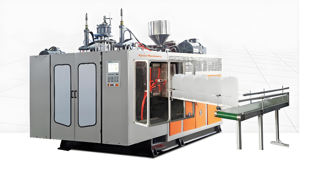

I. Overview
Most faults of extrusion blow molding machines occur in the extrusion system, blow molding system, hydraulic system, electrical control system, and cooling system, with core causes including equipment aging, improper parameter settings, fluctuations in raw material properties, and lack of maintenance. This article focuses on high-frequency faults in production, analyzing from five dimensions: “Fault Phenomenon – Root Causes – Troubleshooting Steps – Solutions – Preventive Measures”, balancing versatility and industry practicality to help quickly locate problems and reduce downtime losses.
II. Fault Analysis by System
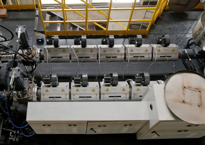
2.1 Extrusion System Faults
The extrusion system is the core of plasticization and molding. Faults directly affect product quality (e.g., wall thickness, strength) and production efficiency. High-frequency issues are as follows:
Fault 1: Unstable Extrusion Capacity
- Fault Phenomenon: Extrusion capacity fluctuation > ±3% per unit time, leading to large product weight deviation and uneven wall thickness.
- Root Causes:
- Excessive moisture content in raw materials (>0.2%) or excessive impurities, resulting in uneven plasticization;
- Severe wear of screw/barrel (clearance >0.08mm) causing material backflow;
- Damaged heating coils or faulty temperature controllers, leading to barrel temperature fluctuations exceeding ±5℃;
- Blockage in the feeding system or unstable rotation speed (frequency converter failure);
- Faulty melt pressure sensor causing distorted signal feedback.
- Troubleshooting Steps:
- Test raw material moisture content (using a moisture analyzer) and observe if there is agglomeration at the barrel feed port;
- Dismantle and inspect the screw/barrel, measure the clearance (standard ≤0.05mm), and check for surface wear marks;
- Verify the on/off status of each heating coil and calibrate the temperature controller (compare actual temperature with displayed value);
- Check if the feeding machine’s spiral blades are blocked and test the stability of the frequency converter’s output frequency;
- Calibrate the melt pressure sensor (compare with a standard pressure gauge).
- Solutions:
- Dry raw materials (temperature 80-120℃, time 2-4 hours) and filter impurities (install 50-80 mesh filter);
- Repair the screw/barrel (chromium plating or nitriding treatment) for slight wear, or replace directly for severe wear;
- Replace damaged heating coils, repair/replace temperature controllers, and ensure temperature fluctuation ≤±2℃;
- Clear blockages in the feeding machine and overhaul the frequency converter (tighten wiring or replace modules);
- Calibrate or replace the melt pressure sensor to ensure normal signal transmission.
- Preventive Measures:
- Test raw material moisture content before warehousing and establish batch test records;
- Check the screw/barrel clearance every 1,000 operating hours and clean carbon deposits regularly (every 2,000 hours);
- Calibrate temperature controllers and sensors monthly and keep spare key heating coils.
Fault 2: Abnormal Melt Temperature
- Fault Phenomenon: Melt temperature too high (burning, discoloration) or too low (insufficient plasticization, cold spots on products).
- Root Causes:
- Unreasonable temperature settings (e.g., barrel temperature exceeding 220℃ for PE);
- Short-circuited or poorly connected heating coils, or misadjusted PID parameters of temperature controllers;
- Mismatched screw length-diameter ratio (e.g., using a screw with L/D=24:1 for processing PC);
- Blocked cooling water channels in the barrel leading to poor heat dissipation;
- Excessively long residence time of materials in the barrel (no cleaning after shutdown).
- Solutions:
- Adjust temperature according to raw material properties (PE: 160-200℃; PP: 180-220℃; PC: 260-300℃);
- Replace faulty heating coils, re-adjust PID parameters of temperature controllers (proportional P=5-10, integral I=10-20);
- Replace with an adaptive screw (e.g., a barrier screw with L/D≥30:1 for PC);
- Unclog cooling water channels (clean with descaling agent) and ensure inlet water temperature ≤35℃;
- Empty materials in the barrel when shutdown exceeds 30 minutes to avoid retention and burning.
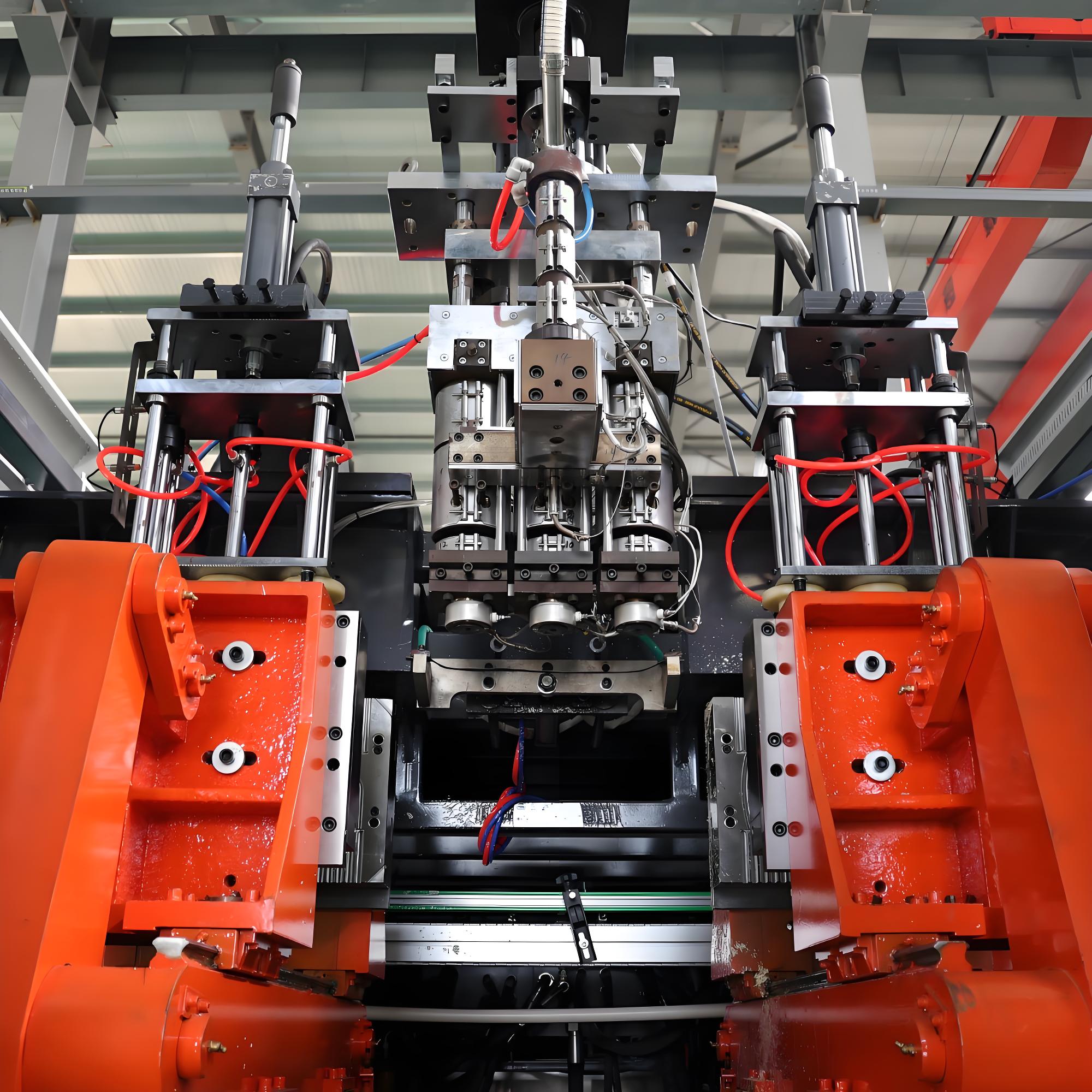
2.2 Blow Molding System Faults
The blow molding system directly determines product forming quality. Core faults focus on mold clamping, blowing, and mold-related links:
Fault 1: Insufficient/Unstable Clamping Force
- Fault Phenomenon: Mold loosening and flash after clamping, or large fluctuations in clamping pressure, leading to severe product flash.
- Root Causes:
- Insufficient hydraulic system pressure (set value lower than required by the product’s projected area);
- Worn or leaking hydraulic pump, or stuck relief valve;
- Aging or damaged seals in the mold clamping cylinder causing internal leakage;
- Mold parallelism deviation (>0.03mm);
- Misadjusted parameters of the servo drive system (for servo-type equipment).
- Troubleshooting Steps:
- Verify the set clamping pressure (calculation formula: Clamping Force (kN) = Product Projected Area (cm²) × Safety Factor (1.2-1.5) × Melt Pressure (MPa));
- Test the hydraulic pump outlet pressure and observe if there is abnormal leakage from the relief valve;
- Dismantle the mold clamping cylinder and check if seals (O-rings, gaskets) are aged or damaged;
- Measure mold parallelism with a dial indicator and check the wear of guide pillars and bushings;
- Review servo drive parameters (e.g., torque limit, position loop gain).
- Solutions:
- Reset the clamping pressure according to the formula to meet production requirements;
- Repair the hydraulic pump (replace worn parts) and clean or replace the relief valve;
- Replace aging seals, reassemble the cylinder, and bleed air;
- Adjust mold parallelism and replace worn guide pillars and bushings (clearance ≤0.02mm);
- Re-adjust servo parameters to ensure stable mold clamping action.
- Preventive Measures:
- Check the stability of hydraulic system pressure weekly and clean hydraulic filters monthly;
- Replace hydraulic oil every 6 months (recommend 46# anti-wear hydraulic oil) and inspect seal conditions;
- Calibrate mold parallelism after installation to avoid eccentric load operation.
Fault 2: Uneven Product Wall Thickness
- Fault Phenomenon: Wall thickness deviation >5% in the same cross-section of the product, with local thinness (prone to cracking) or thickness (wasting raw materials).
- Root Causes:
- Blocked or worn die head flow channels causing uneven material distribution;
- Unstable blowing pressure/speed (pressure fluctuation >0.2MPa);
- Parison sagging (insufficient cooling or excessive extrusion speed);
- Faulty Electronic Wall Thickness Control System (EWCS) (e.g., faulty sensor, stuck actuator);
- Worn mold cavity or poor exhaust.
- Solutions:
- Dismantle the die head, clean carbon deposits in flow channels, and repair worn flow channel surfaces (polishing treatment);
- Check air storage tank pressure, replace faulty pressure reducing valves/solenoid valves, and ensure stable blowing pressure (fluctuation ≤±0.1MPa);
- Reduce extrusion speed (≤5m/min) and enhance parison cooling (increase cooling water flow or lower water temperature);
- Calibrate the wall thickness sensor, clear blockages in the actuator (e.g., needle valve), and re-adjust EWCS parameters;
- Polish the mold cavity and unclog exhaust grooves (width 0.1-0.2mm, depth 1-2mm).
2.3 Hydraulic System Faults
The hydraulic system provides power for the equipment. Faults are mostly manifested as abnormal pressure, flow, and leakage, making it one of the systems with high downtime rates:
Fault 1: Hydraulic System Leakage
- Fault Phenomenon: Rapid drop in oil tank level, oil stains at the connections of the machine body or pipelines, and decrease in system pressure.
- Root Causes:
- Loose pipeline joints, aging or damaged seals;
- Worn seals in hydraulic pumps, cylinders, directional valves, and other components;
- Mismatched hydraulic oil viscosity (e.g., using hydraulic oil lower than 46#) or severe contamination;
- Excessively high system pressure (exceeding the rated pressure by more than 10%).
- Solutions:
- Tighten loose joints and replace aging/damaged seals (recommend fluororubber material for oil and high-temperature resistance);
- Dismantle faulty components, replace seals, reassemble, and bleed air;
- Replace with compliant hydraulic oil (46# or 68# anti-wear hydraulic oil) and clean the oil tank and filter;
- Adjust the relief valve to control the system pressure within the rated range (generally ≤16MPa).
Fault 2: Overheating of Hydraulic Oil
- Fault Phenomenon: Oil temperature exceeds 60℃, the system produces noise, pressure is unstable, and even triggers overheating protection to shut down.
- Root Causes:
- Blocked cooler or faulty cooling fan leading to reduced heat dissipation efficiency;
- Insufficient hydraulic oil level (below the minimum scale) resulting in insufficient heat dissipation area;
- Severe internal leakage in the system (e.g., cylinder internal leakage) converting energy loss into heat;
- High ambient temperature (>35℃) and poor ventilation.
- Solutions:
- Clean the cooler (using a high-pressure water gun or descaling agent) and repair/replace the cooling fan;
- Supplement hydraulic oil to the standard level (between the maximum and minimum scales);
- Inspect and repair internal leakage components (e.g., replace cylinder seals);
- Improve workshop ventilation (install exhaust fans) and avoid long-term operation of the equipment in high-temperature environments.
2.4 Electrical Control System Faults
The control system is the “brain” of the equipment. Faults are mostly manifested as operational failure and abnormal actions. Troubleshooting needs to combine PLC programs and circuit principles:
Fault 1: PLC Unresponsive/Action Disorder
- Fault Phenomenon: HMI (Human-Machine Interface) black screen, unresponsive keys, or equipment actions inconsistent with operating instructions.
- Root Causes:
- PLC power supply failure (e.g., burned power module, unstable voltage);
- Loose or poorly connected communication lines (e.g., communication line between PLC and HMI);
- Lost or damaged PLC program (e.g., exhausted backup battery);
- Faulty input/output (I/O) modules causing abnormal signal transmission;
- Faulty external sensors (e.g., proximity switches, pressure sensors) providing incorrect feedback signals.
- Troubleshooting Steps:
- Check the PLC power supply voltage (standard 220V AC or 24V DC) and observe if the power module indicator is normal;
- Tighten communication line joints and replace damaged communication lines;
- Check the PLC backup battery (voltage ≥3V), replace if insufficient, and re-import the program;
- Use a multimeter to test the output voltage of the I/O module to determine if the module is faulty;
- Test external sensors one by one and observe if the PLC input signal is normal (monitorable on HMI).
- Solutions:
- Replace the faulty power module and install a voltage stabilizer to ensure stable voltage;
- Reconnect communication lines and replace damaged wires;
- Replace the PLC backup battery and restore the program through backup;
- Replace the faulty I/O module and reconfigure module parameters;
- Calibrate or replace faulty sensors to ensure accurate signal feedback.
Fault 2: Servo Driver Alarm
- Fault Phenomenon: The servo driver displays an alarm code (such as overload ALM, overvoltage OV, excessive position deviation), and the equipment shuts down.
- Common Alarm Causes and Solutions:Alarm CodeRoot CauseSolutionOverload (ALM)Excessive load, motor jamming, poor heat dissipation of the driverReduce load, troubleshoot motor jamming, clean the driver’s cooling fanOvervoltage (OV)Excessively high input voltage, faulty regenerative resistorCheck power grid voltage, replace the regenerative resistorExcessive Position DeviationToo low position loop gain, stuck mechanical transmissionIncrease position loop gain, check the wear of lead screws/gearboxesEncoder FaultLoose encoder wiring, damaged encoderTighten wiring, replace the encoder
2.5 Cooling System Faults
The cooling system affects product shaping and equipment heat dissipation. Faults easily lead to product deformation and reduced production efficiency:
Fault 1: Insufficient Product Cooling
- Fault Phenomenon: The product deforms after demolding, has a large shrinkage rate, and has depressions or bubbles on the surface.
- Root Causes:
- Excessively high cooling water temperature (>25℃) or insufficient cooling water flow;
- Blocked or unreasonably arranged cooling water channels in the mold;
- Too short cooling time (less than product wall thickness × 1.5 seconds);
- Insufficient blowing cooling pressure (<0.3MPa).
- Solutions:
- Lower the cooling water temperature (control at 15-20℃) and increase the cooling water flow (ensure mold inlet water pressure ≥0.4MPa);
- Unclog cooling water channels with a high-pressure water gun or descaling agent and optimize the channel layout (ensure uniform cooling of each cavity);
- Extend the cooling time (adjust according to product wall thickness, e.g., cooling time ≥7.5 seconds for 5mm wall thickness);
- Increase the blowing cooling pressure (0.3-0.6MPa) and optimize the position of the air nozzle.
III. Emergency Handling Skills
- Shutdown Priority Principle: Press the emergency stop button immediately when a fault occurs to avoid fault expansion (such as equipment jamming caused by flash);
- Fault Recording: Record the fault phenomenon, alarm code, occurrence time, and operating conditions (such as raw material model, parameter settings) to facilitate subsequent troubleshooting;
- Simple Troubleshooting: First check whether the power supply, air supply, and water supply are normal, then check wearing parts (such as sensors, seals), and finally conduct in-depth inspection of complex systems;
- Spare Parts Reserve: Key spare parts (such as heating coils, seals, sensors, PLC backup batteries) should be reserved in advance to shorten downtime.
IV. Daily Maintenance and Fault Prevention
4.1 Daily Maintenance
- Check raw material moisture content and cleanliness to meet production requirements;
- Inspect hydraulic oil and lubricating oil levels, and clean oil stains and debris on the equipment surface;
- Test the normalcy of pressure and temperature in each system, and observe for leakage and abnormal noise;
- Clean accumulated materials on the mold surface and check if the exhaust grooves are unobstructed.
4.2 Weekly Maintenance
- Clean hydraulic system filters and cooler screens;
- Check the tightness of heating coil and sensor wiring;
- Lubricate moving parts of the equipment (such as guide pillars, lead screws) and add lubricating oil;
- Calibrate temperature controllers and pressure sensors.
4.3 Monthly Maintenance
- Inspect the wear of the screw/barrel and clean carbon deposits;
- Check the status of hydraulic pumps, cylinders, and seals, and replace aging components;
- Test the operational stability of the servo system and calibrate position accuracy;
- Backup the PLC program and check the backup battery level.
4.4 Annual Maintenance
- Fully disassemble key equipment components (such as die head, hydraulic pump, servo motor) for in-depth maintenance;
- Replace hydraulic oil and lubricating oil, and clean the oil tank;
- Test mold accuracy and repair worn cavities;
- Conduct a comprehensive inspection of the electrical system and replace aging wires and contactors.
V. Conclusion
The troubleshooting of extrusion blow molding machines should follow the principle of “first phenomenon then essence, first simple then complex, first mechanical then electrical“, with the core being “prevention first and rapid response”. By establishing a standardized maintenance system, accurately recording equipment operation data, and reserving key spare parts, the fault rate can be significantly reduced; mastering the troubleshooting logic and solutions for common faults can effectively shorten downtime and ensure production continuity.
For complex faults (such as PLC program faults, severe wear of core components), it is recommended to contact the equipment supplier or professional technicians for maintenance to avoid secondary damage caused by incorrect operation.