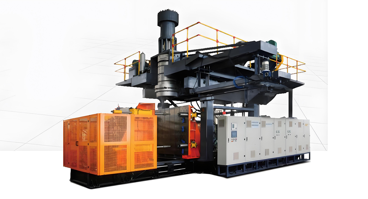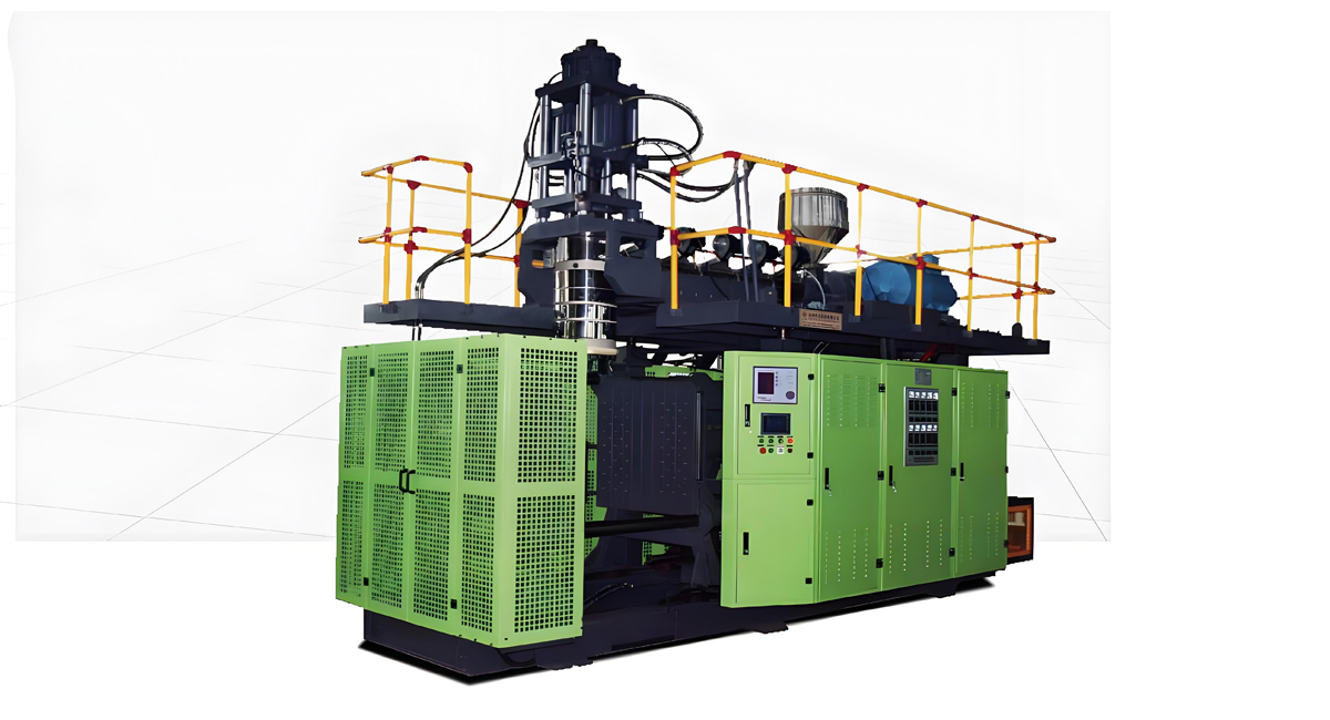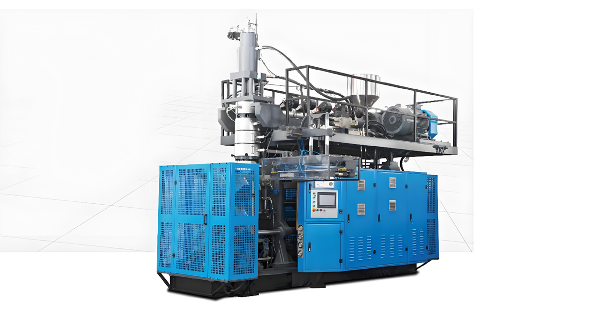
Extrusion blow molding machines are the backbone of hollow plastic product manufacturing, serving industries from food & beverage packaging and daily chemical containers to industrial drums and automotive components. For production facilities, unplanned downtime caused by machine jams is one of the most costly and frustrating operational challenges. A single jam event can lead to hours of lost production, significant raw material waste, defective products, and even permanent damage to critical components like the screw, barrel, or die head. For facilities running 24/7 production schedules, recurring jams can directly impact delivery deadlines, customer satisfaction, and overall profit margins. As a leading global manufacturer of extrusion blow molding equipment with over two decades of R&D and field service experience, Apollo has supported thousands of clients worldwide in troubleshooting and resolving jam-related issues, while designing machines with built-in anti-jam features to minimize downtime risks. This comprehensive guide breaks down the common types of blow molding machine jams, their root causes, step-by-step troubleshooting and repair methods, long-term preventive maintenance strategies, and cost-benefit analysis of upgrading to optimized equipment. Whether you are a production manager, maintenance technician, or business owner, this guide will help you reduce jam frequency, cut operational costs, and maximize the production efficiency of your extrusion blow molding line.
Many facilities underestimate the long-term impact of frequent minor jams, dismissing them as an unavoidable part of plastic production. In reality, most jam issues are preventable through proper process control, regular maintenance, and optimized equipment design. Understanding why jams occur and how to resolve them quickly is critical for any production team aiming to improve overall equipment effectiveness (OEE) and reduce production costs. Throughout this guide, we will reference real-world field service data from Apollo to provide practical, actionable solutions that have been proven effective across hundreds of production facilities globally.
1. Common Types of Jams and Their Impact on Production
Jams can occur at multiple points along the extrusion blow molding process, each with different causes, symptoms, and repair requirements. Identifying the type and location of a jam is the first step toward quick resolution. Below are the most common categories of blow molding machine jams, along with their typical signs and operational impacts.
1.1 Hopper & Feed Throat Jams
Hopper jams, also known as feed bridging, are one of the most frequently encountered jam issues in extrusion blow molding machines. This type of jam occurs at the material hopper and feed throat, where raw plastic pellets or regrind fail to flow smoothly into the screw flights. The most visible sign of a hopper jam is a sudden drop in extruder output, or complete stoppage of material feeding, even when the screw continues to rotate. In mild cases, the machine will produce uneven parisons and inconsistent product weight; in severe cases, the screw can run dry for extended periods, leading to overheating and material degradation inside the barrel. Hopper jams are often caused by irregularly shaped regrind material, high moisture content causing pellets to clump together, or poorly designed feed throats with narrow openings that trap large material chunks. For facilities using high proportions of recycled material, hopper jams tend to occur much more frequently, increasing the workload for operating staff and reducing overall production efficiency. While generally easy to fix, frequent recurring hopper jams can add up to significant lost production time over the course of a year.
1.2 Screw & Barrel Jams
Screw and barrel jams are more serious and costly than hopper jams, as they involve the core plasticizing unit of the extrusion blow molding machine. This type of jam occurs when molten or partially melted plastic gets stuck inside the barrel, preventing the screw from rotating normally. Common signs include a sudden spike in extruder drive motor current, abnormal noise from the gearbox, and complete cessation of material output from the die head. Screw jams can be caused by multiple factors: foreign objects mixed into the raw material, excessively low barrel temperatures leading to incomplete plasticization, severe wear of the screw or barrel causing material to get stuck in gaps, or sudden shutdowns that leave molten plastic to cool and solidify inside the barrel. If not handled properly, screw jams can cause permanent damage: the screw can be bent or broken, the barrel inner wall can be scratched, and in extreme cases, the drive motor or gearbox can burn out, requiring expensive repairs and weeks of downtime. Screw and barrel jams are among the most expensive types of blow molding failures, both in terms of repair costs and lost production.
1.3 Die Head & Parison Jams
Die head jams occur in the extrusion die assembly, which shapes the molten plastic into a continuous parison. This type of jam typically presents as uneven parison thickness, partial blockage of the die opening, or complete stoppage of material flow from the die. In many cases, die head jams are caused by carbonized material buildup (also known as die lip buildup) that accumulates over time on the inner flow channels of the die head. Carbonized particles can also break off and get stuck in the die gap, creating defects in the parison and final products. Other causes include foreign objects in the melt, improper die gap adjustment, or sudden temperature drops in the die head that cause the plastic to solidify prematurely. Die head jams not only affect product appearance and dimensional accuracy, but also lead to increased flash waste and higher scrap rates. If left unaddressed, long-term die head buildup can cause permanent damage to the precision-machined die surfaces, requiring costly rework or replacement. For high-precision applications like food packaging and cosmetic containers, even minor die buildup that causes subtle surface defects can result in entire production batches being rejected by customers.
1.4 Pinch-off, Trimmer & Downstream Jams
Jams can also occur in the clamping, trimming, and downstream sections of the blow molding line, even when the extrusion unit is operating normally. Pinch-off jams happen when excess flash or partially formed product gets stuck in the mold pinch-off area, preventing the mold from closing fully. This is often caused by misaligned mold halves, worn pinch-off edges, or excessively thick parison walls. Trimmer jams occur in the automatic flash trimming unit, where cut-off waste material gets tangled in the cutting blades or conveyor system. Downstream jams can also happen on take-out conveyors or cooling racks, where finished products pile up and cause blockages. While these downstream jams are usually less damaging to the core machine, they still cause production stoppages and require operator intervention to clear. For high-speed fully automatic production lines, frequent downstream jams can become a major bottleneck limiting overall output. Many facilities focus all their jam prevention efforts on the extruder, but overlook downstream stations, which can account for 30 to 40% of all unplanned downtime events.
1.5 Quantifiable Impacts of Jams on Production Costs
The financial impact of extrusion blow molding machine jams goes far beyond the obvious repair costs. For a typical mid-sized production facility running a single blow molding line, every hour of unplanned downtime results in direct production losses of 100 to 300 kilograms of finished product, translating to $150 to $500 in lost gross profit based on average industry margins. Direct material waste from each jam event ranges from 5 to 25 kilograms of plastic resin, as material trapped in the barrel and die head often becomes degraded or contaminated and must be scrapped. Labor costs also add up: clearing a jam usually requires 1 to 2 maintenance technicians working for 1 to 4 hours, plus production line operators assisting with cleanup and restart procedures. Indirect costs include reduced product quality from inconsistent processing parameters after restart, potential delivery delays for customer orders, and accelerated wear and tear on machine components from repeated jam events. For facilities experiencing 3 to 6 jam events per month, total annual losses from downtime, waste, and repairs can easily reach $15,000 to $40,000 per production line. For high-volume facilities running multiple lines, these losses scale up significantly, making jam prevention a high-priority operational improvement initiative. When you factor in the hidden costs of lower employee morale and potential damage to customer relationships from late deliveries, the true cost of recurring jams is even higher.
2. Root Causes of Extrusion Blow Molding Machine Jams
To effectively resolve and prevent jams, it is critical to identify their underlying root causes rather than only addressing the immediate symptoms. Jam issues in blow molding machines almost always stem from one or more of four categories: raw material problems, equipment wear and design flaws, incorrect process parameter settings, and improper operation & maintenance practices. Understanding these causes helps production teams target their troubleshooting efforts and implement long-term corrective actions.
2.1 Raw Material Related Causes
Raw material issues are the most common trigger of blow molding machine jams, especially for facilities that use recycled or regrind material. First, moisture contamination is a frequent culprit: hygroscopic resins like PET, ABS, and nylon absorb moisture from the air, and if not properly dried before processing, the moisture will vaporize inside the hot barrel, creating bubbles and uneven melt flow that can lead to blockages. For polyolefins like HDPE and PP, high moisture content can also cause clumping of pellets in the hopper, leading to feed bridging jams. Second, foreign contaminants in raw materials are a major cause of severe jams. Metal fragments, wood chips, dust, or other hard impurities mixed into resin pellets can get wedged between the screw and barrel, or stuck in the die head gap, causing immediate blockage and even permanent component damage. Third, inconsistent material properties can lead to jams. Using resin grades with significantly different melt flow indexes (MFI) without adjusting process parameters can cause uneven plasticization: low MFI material may not melt fully and cause blockages, while overly high MFI material can cause surging and uneven output. Fourth, high proportions of regrind or recycled material increase jam risk. Irregularly shaped regrind particles are more prone to bridging in the hopper, and contaminants or degraded material in regrind can cause buildup in the barrel and die head. Facilities using more than 30% regrind in their formulation typically experience 2 to 3 times more jam events than those using 100% virgin resin. Even small amounts of contaminated or off-spec regrind can cause significant production disruptions.
2.2 Equipment Condition & Design Related Causes
The condition and design of the extrusion blow molding machine itself play a decisive role in jam frequency. First, wear of the screw and barrel is a leading cause of recurring jams in older machines. Over years of continuous operation, the screw flights and barrel inner wall gradually wear down, increasing the gap between them. This reduces the plasticizing efficiency and conveying capacity of the screw, leading to uneven melt flow and increased risk of material buildup and blockage. Severely worn screws can also cause material to get trapped in the gaps, leading to thermal degradation and carbonization that worsens jam problems over time. Second, faulty temperature control systems cause jams by creating inconsistent heating. Failed heating bands, inaccurate temperature sensors, or poorly calibrated PID controllers can result in localized low-temperature zones in the barrel or die head, where plastic does not fully melt and solidifies into chunks that cause blockages. Inconsistent temperature also leads to uneven melt viscosity, which disrupts stable material flow. Third, poorly designed feed systems increase jam risk. Hoppers with steep or irregular side walls, or feed throats with insufficient opening size, are prone to material bridging. Machines without forced feeding or agitation devices are particularly susceptible to jams when processing regrind or low-bulk-density materials. Fourth, worn or misaligned die head components contribute to jams. Over time, die lips can become nicked or uneven, creating spots where material can accumulate and carbonize. Misaligned die mandrels can also cause uneven flow patterns that promote buildup formation. Many low-cost blow molding machines on the market cut corners on material quality and machining precision for screw and barrel components, resulting in much faster wear and significantly higher jam frequency compared to well-built industrial-grade machines like those manufactured by Apollo.
2.3 Process Parameter Related Causes
Incorrect or poorly optimized process parameters are another major category of jam causes, and often the easiest to correct. First, improper barrel and die head temperature settings are a common trigger. Setting temperatures too low for the specific resin type prevents complete plasticization, leaving semi-solid plastic chunks that can block the die or get stuck in the screw flights. On the other hand, setting temperatures excessively high can cause thermal degradation of the resin, leading to carbonized particles that build up in the flow channels and eventually cause jams. Second, mismatched screw speed and feed rate cause unstable processing. If the screw rotates too fast relative to the material feed rate, the screw can run partially empty, creating uneven melt pressure and temperature fluctuations that lead to blockages. Conversely, overfeeding the extruder beyond its plasticizing capacity can cause material to back up in the feed zone, leading to hopper bridging and screw overload jams. Third, insufficient or improperly set back pressure contributes to jams. Back pressure is used to improve melt homogeneity and vent trapped air, but too little back pressure can result in uneven melt density and trapped air bubbles that cause flow disruptions. Excessively high back pressure, however, increases shear heat and can cause material degradation, leading to carbon buildup and eventual jams. Fourth, improper cooling settings for the die or feed throat cause problems. Over-cooling the feed throat can cause condensation and moisture buildup in the material, while insufficient cooling of the die head can lead to excessive melt temperature and degradation. Many facilities set process parameters based on general guidelines rather than optimizing them for their specific material formulation and product design, which leaves them vulnerable to preventable jam issues. Even small adjustments to temperature or speed profiles can often resolve recurring minor jams.
2.4 Operation & Maintenance Related Causes
Many recurring jam issues stem from inadequate daily operation and maintenance practices. First, improper machine startup and shutdown procedures cause jams. Starting the screw rotating before the barrel has reached the correct set temperature forces cold, hard plastic through the system, which can overload the drive and cause jams. Similarly, shutting down the machine without properly purging all molten material from the barrel and die head leaves plastic to cool and solidify inside, causing a hard jam when the machine is next started. Second, infrequent or improper cleaning procedures lead to buildup over time. When changing material types or colors, incomplete purging leaves residual material in the barrel and die head, which can degrade and carbonize over subsequent production runs, gradually narrowing flow channels and eventually causing jams. Many facilities skip regular deep cleaning of the die head and screw, allowing carbon buildup to accumulate for months until it causes a major blockage. Third, lack of regular preventive maintenance leads to avoidable failures. Failing to inspect and replace worn heating bands, calibrate temperature sensors, or lubricate moving components on schedule increases the likelihood of sudden equipment malfunctions that cause jams. Fourth, untrained operators contribute to jam events. Operators who do not understand basic machine operation principles may make incorrect parameter adjustments, fail to notice early warning signs of impending jams, or respond incorrectly when a jam occurs, turning a minor issue into a major breakdown. In our experience at Apollo, roughly 40% of all customer-reported jam incidents are directly caused by operator error or inadequate maintenance practices. This is an area where facilities can see dramatic improvement with relatively little investment in training and standardized procedures.
3. Step-by-Step Guide to Diagnosing and Resolving Jams
When a jam occurs, following a standardized, safety-first troubleshooting procedure is critical to resolve the issue quickly while minimizing risk of injury and further equipment damage. The following step-by-step guide is based on Apollo’s decades of field service experience and is applicable to most extrusion blow molding machine models. Always prioritize personnel safety over speed of repair, and ensure all work is performed by trained maintenance staff.
3.1 Pre-Troubleshooting Safety Procedures
Before attempting to diagnose or clear any jam, mandatory safety steps must be completed to protect operating and maintenance personnel. First, press the emergency stop button immediately to halt all machine movements, then turn off the main power supply to the extruder drive, clamping system, and downstream equipment. Follow your facility’s lockout/tagout (LOTO) procedures to ensure the machine cannot be accidentally restarted while maintenance work is in progress. Never rely solely on software stop commands; always physically isolate power to the machine. Second, allow sufficient time for the machine to cool if working on high-temperature components. Barrel and die head surfaces can reach temperatures of 200 to 300 degrees Celsius, causing severe burns if touched directly. Wear appropriate personal protective equipment (PPE): heat-resistant gloves, safety glasses, face shields, and heat-proof work boots. Third, never attempt to reach into moving components or open safety guards while the machine is powered on. All safety interlocks must remain functional; never bypass or disable safety switches to speed up repair work. Fourth, assign a dedicated safety observer for complex repair jobs, to monitor conditions and alert staff if any hazards arise. Following these safety protocols may add a small amount of time to the repair process, but it prevents serious workplace injuries that have far greater human and financial costs. Apollo includes comprehensive safety training as part of every new machine installation, to ensure all customer personnel understand proper safe work procedures for blow molding machine operation and maintenance.
3.2 Step 1: Locate and Assess the Jam Severity
The first diagnostic step is to identify the exact location and severity of the jam, which determines the appropriate repair method. Start by inspecting the hopper and feed throat first, as this is the easiest location to access and the most common source of jams. Check if material is bridging in the hopper and not flowing down into the screw. If the hopper is full but no material is being conveyed, the jam is likely in the feed zone. Next, check the extruder drive motor current reading: a sudden spike in current that triggers an overload alarm usually indicates a jam in the screw or barrel, where the motor is struggling to turn the screw against blocked material. Normal or low current with no output usually points to a feed hopper jam, where the screw is spinning but not getting any material to convey. Then, inspect the die head: look for partial or complete blockage of the die opening, and check for carbonized buildup around the die lips. If material is flowing from the die but in an uneven or intermittent pattern, the jam may be partial, located inside the die head flow channels. Finally, assess severity: minor partial jams can often be cleared by adjusting process parameters and purging, while severe full blockages require full disassembly and manual cleaning. Document all observations and the current machine parameters to help identify the root cause after the jam is cleared. Taking photos or notes of the jam location and material condition can also be very helpful for future reference and for troubleshooting recurring issues with your equipment supplier.
3.3 Step 2: Resolving Hopper & Feed Throat Jams
Hopper jams are generally the easiest to resolve and do not require full machine disassembly. First, stop the screw rotation and turn off the feeder if your machine has a separate metering feeder. Never try to clear a bridging jam by reaching into the hopper with your hands while the screw is running, as this poses a severe injury risk. For minor bridging, you can gently tap the sides of the hopper with a rubber mallet to dislodge the clumped material. Do not use heavy metal hammers, as they can dent or damage the hopper walls and feed throat, making bridging problems worse in the future. If tapping does not work, use a long, rigid plastic or wooden rod to carefully break up the bridged material from the top of the hopper. Always keep your hands outside the hopper and use the tool to reach down into the material. For persistent recurring hopper jams, you may need to temporarily reduce the regrind proportion in your material blend, or sift out oversized regrind chunks before feeding. After clearing the jam, restart the feeder and screw at low speed first, and monitor material flow for several minutes to ensure the jam is fully resolved before returning to full production speed. To prevent future hopper jams, consider installing a hopper agitator or vibratory feeder, which continuously agitates the material to prevent bridging formation. Apollo offers optional anti-bridging hopper upgrades for all its blow molding machine models, which can reduce hopper jam frequency by over 90% for facilities processing high proportions of regrind material. This is one of the most cost-effective upgrades you can make if feed bridging is a recurring issue at your facility.
3.4 Step 3: Resolving Screw & Barrel Jams
Screw and barrel jams require more careful handling to avoid damaging the precision screw and barrel components. First, confirm the jam is located in the barrel by checking motor current and feed flow. Never attempt to force a jammed screw to rotate by increasing motor torque or using external leverage, as this can bend the screw, strip the gearbox gears, or burn out the drive motor, resulting in thousands of dollars in repair costs. For mild screw jams where the screw can still rotate slowly at low speed, the recommended method is heat purging: increase the barrel temperature settings by 20 to 30 degrees Celsius above the normal processing temperature for your resin, and allow sufficient time for the blocked material to fully melt. Once the material has softened, run the screw at the lowest possible speed (5 to 10 rpm) to slowly purge the softened material out through the die head. Continue purging until all degraded or contaminated material has been extruded, and the melt flow appears uniform and consistent. For more severe jams where the screw cannot rotate at all, full disassembly is required. This involves removing the die head, then using a specialized screw puller tool to extract the screw from the feed end of the barrel. Once the screw is removed, manually clean all residual plastic and carbonized material from the screw flights and the inner wall of the barrel using copper scrapers, brass brushes, and appropriate cleaning agents. Never use steel tools that can scratch or gouge the precision surfaces of the screw and barrel, as even minor scratches can cause future buildup and jams. After cleaning, inspect the screw and barrel for signs of excessive wear, damage, or corrosion. If wear is beyond acceptable tolerance levels, repair or replacement of the components may be necessary to prevent recurring jams. Reassemble the machine carefully, ensuring proper alignment of the screw and barrel, and perform a slow test run before returning to full production. Apollo service engineers are trained to handle even the most severe screw and barrel jams, and can provide on-site assistance for complex disassembly and repair jobs. We also offer screw refurbishment services to restore worn screws to like-new condition at a fraction of the cost of replacement.
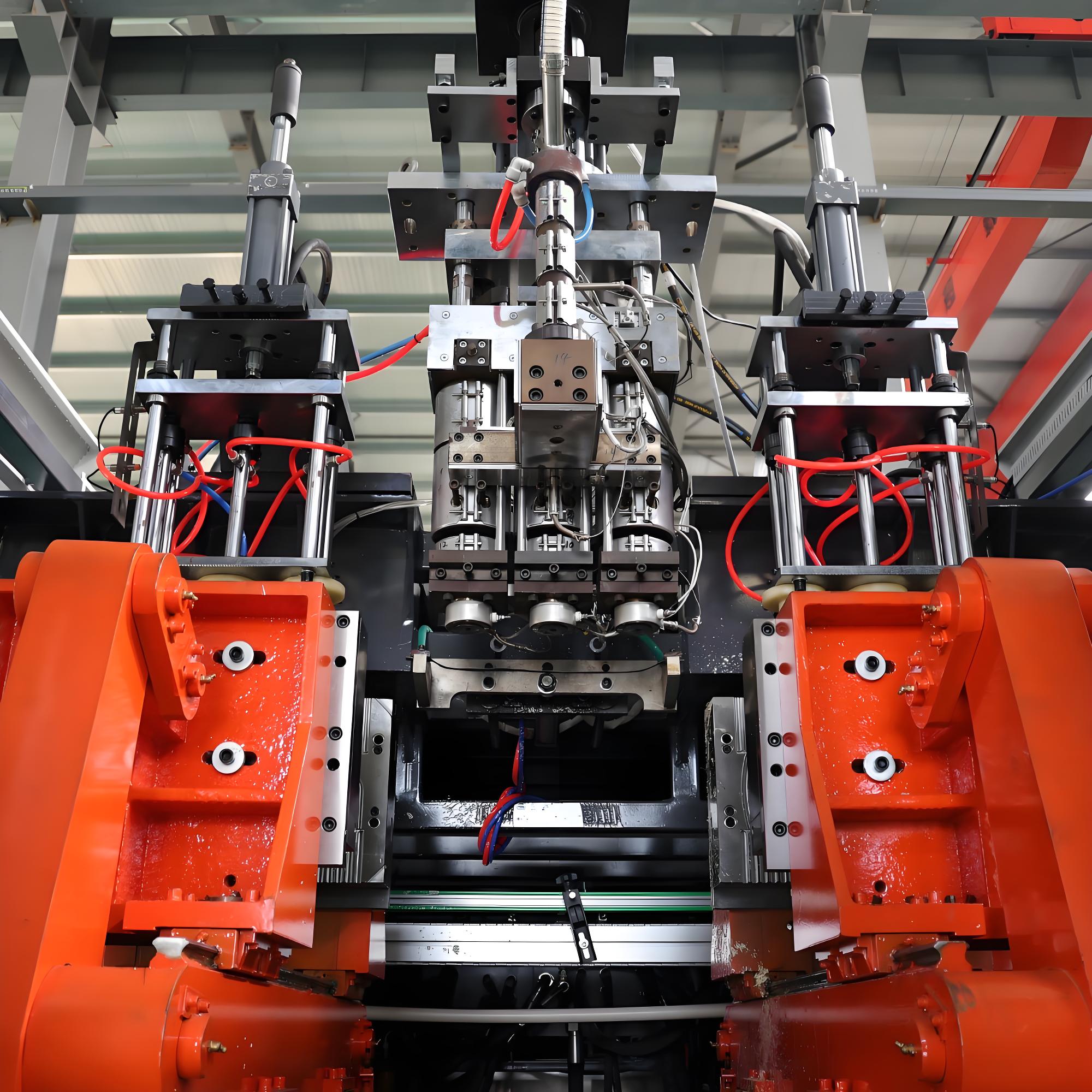
3.5 Step 4: Resolving Die Head Jams & Buildup
Die head jams related to carbon buildup are best addressed through a combination of heat purging and manual cleaning. First, increase the die head temperature by 15 to 25 degrees Celsius to soften the accumulated carbonized material. Run the extruder at low speed with a clean purge material (usually high-MFI HDPE or specialized purge compound) to push out softened buildup from the die flow channels. For minor die lip buildup, you can carefully clean the outer die surface while the machine is running at low speed, using a brass scraper tool specifically designed for die cleaning. Always exercise extreme caution when working near an operating die head, and wear proper heat protection. Never use sharp steel tools that can chip or scratch the die lip surfaces, as even a small nick will cause permanent flow defects in the parison. For severe internal die head buildup that cannot be cleared through purging, full disassembly and cleaning is required. After shutting down and cooling the die head safely, disassemble the die mandrel, die body, and adjusting rings. Scrape off all carbonized residue from the flow channels using soft copper tools, taking care not to damage the precision-machined surfaces. For stubborn carbon deposits, you can use a commercial plastic die cleaning solution, or burn off residue in a controlled temperature oven (follow the oven manufacturer’s safety guidelines). After cleaning, inspect all sealing surfaces and die lips for damage, wear, or corrosion. Reassemble the die head carefully, ensuring proper alignment and torque of all fasteners to prevent leaks. After restarting, perform a gradual warm-up cycle and adjust the die gap evenly to ensure uniform parison flow. Apollo blow molding machines feature optimized flow channel design with smooth, dead-zone-free internal surfaces, which significantly reduces material stagnation and carbon buildup formation. This design extends the required interval between full die head cleanings by 2 to 3 times compared to conventional die designs, reducing maintenance downtime and improving overall production efficiency. For customers producing highly degradable materials or running long continuous production campaigns, we also offer optional die head coatings that further reduce material adhesion and buildup.
3.6 Step 5: Resolving Downstream Pinch-off & Trimmer Jams
Downstream jams in the mold clamping and trimming sections require a different troubleshooting approach. For pinch-off jams where flash or product is stuck in the mold, first ensure the clamping system is fully locked out and cannot close accidentally. Carefully remove the stuck plastic material from the mold cavity and pinch-off edges using appropriate tools. Inspect the pinch-off blades for damage, wear, or misalignment: dull or misaligned pinch-off edges do not cut flash cleanly, leading to excess material buildup and recurring jams. If the pinch-off edges are worn or damaged, they may need to be re-machined or replaced. Check mold alignment: if the two mold halves are not perfectly aligned, the pinch-off edges will not meet evenly, causing uneven flash and frequent jams. Adjust the mold mounting and alignment as needed to ensure perfect closing alignment. For trimmer jams, first clear all tangled flash waste from the cutting blades and conveyor. Inspect the cutting blades for sharpness and alignment: dull blades produce ragged flash edges that are more prone to tangling and jamming. Sharpen or replace blades as needed. Adjust the trimmer speed and timing to match the extrusion cycle, ensuring flash is cut cleanly and removed from the area promptly. For automatic trimmer systems, check that sensors and actuators are functioning correctly to prevent timing errors that cause jams. Many facilities overlook downstream equipment maintenance, focusing all their attention on the extruder. However, keeping trimmer blades sharp and molds properly aligned can eliminate a large percentage of unplanned downtime events with minimal cost and effort. Apollo provides detailed maintenance guidelines for all downstream components as part of our machine documentation, to help customers keep their entire production line running smoothly.
3.7 Post-Repair Restart & Performance Verification
After clearing the jam and reassembling all components, follow a structured restart procedure to ensure the machine returns to stable production safely. First, double-check all safety guards are reinstalled and all safety interlocks are functional. Verify that no tools or cleaning debris have been left inside the machine. Next, perform a gradual temperature ramp-up: heat the barrel and die head to normal processing temperatures, and hold at temperature for sufficient time to ensure all material inside is fully and uniformly melted. Rushing the heat-up process can cause new partial blockages. Then, start the extruder at the lowest possible screw speed, and gradually increase speed over 10 to 15 minutes while monitoring melt pressure, motor current, and parison appearance. Watch for any signs of unusual noise, vibration, or pressure fluctuations that could indicate residual blockage or component damage. Collect initial production samples and inspect them carefully for defects, dimensional accuracy, and visual quality. Compare product quality to pre-jam baseline levels to confirm the machine is operating normally. Finally, document the entire jam event: record the time of occurrence, suspected root cause, repair steps taken, parts replaced, and total downtime. Tracking jam data over time helps identify recurring patterns and prioritize long-term improvement projects. Many facilities skip this documentation step, but it is one of the most valuable tools for continuously reducing jam frequency over time. By analyzing historical jam data, you can identify trends – for example, jams always occurring after material changeovers, or on a particular shift – and target corrective actions accordingly. Apollo service engineers can also help customers analyze their jam data to identify optimization opportunities and recommend targeted equipment or process improvements.
4. Long-Term Preventive Strategies to Eliminate Recurring Jams
While knowing how to clear jams quickly is important, the most cost-effective approach is to prevent jams from occurring in the first place. Implementing systematic preventive measures can reduce jam frequency by 80 to 95%, significantly cutting downtime and maintenance costs. The following four-pronged strategy covers raw material control, process optimization, equipment maintenance, and personnel training, providing a comprehensive framework for jam prevention.
4.1 Strict Raw Material Quality Control
Controlling raw material quality is the first line of defense against extrusion blow molding machine jams. Start by establishing clear incoming material inspection standards for all resin deliveries: check for moisture content, contaminant presence, melt flow index consistency, and pellet size uniformity. Reject any batches that do not meet specifications, as low-quality raw materials are not worth the cost savings when they cause production downtime and scrap. For hygroscopic materials, implement strict drying procedures before processing: use desiccant dryers with accurate dew point control, and verify moisture content with a moisture analyzer before feeding material into the extruder. Proper drying eliminates moisture-related clumping and degradation issues that cause jams. For facilities using regrind or recycled material, implement a material preparation process: screen regrind to remove oversized chunks and foreign contaminants, densify fluffy regrind to improve flow consistency, and blend regrind thoroughly with virgin resin in controlled proportions. Limit the maximum regrind percentage to a level that your equipment can handle reliably, typically 20 to 30% for most standard blow molding applications. Install magnetic separators or metal detectors on the feed hopper to catch any metal fragments that may be mixed into the material, preventing severe screw and die damage from metal contaminants. Finally, store all raw materials properly in a dry, temperature-controlled environment to prevent moisture absorption and contamination before use. Many facilities invest heavily in high-end equipment but cut corners on raw material handling, which ultimately undermines their production efficiency and product quality. Even the best blow molding machine cannot produce consistent, high-quality products from poor-quality raw material. Apollo’s technical team can help customers evaluate their material handling processes and recommend appropriate drying, conveying, and material preparation equipment to minimize jam risks.
4.2 Optimized Process Parameter Management
Standardizing and optimizing process parameters is a low-cost, high-impact way to reduce jam frequency. First, develop formal, documented process recipes for each product and material combination. Include precise settings for barrel zone temperatures, screw speed, feed rate, back pressure, die head temperature, and cooling parameters. These recipes should be developed through systematic testing to find the optimal balance between production output, product quality, and process stability. Once established, restrict parameter adjustment access to trained and authorized personnel only, to prevent inexperienced operators from making incorrect changes that cause process instability and jams. Second, implement standardized startup and shutdown procedures for every production run. For startups, follow a gradual temperature ramp-up schedule and allow sufficient soak time to ensure all material in the barrel is fully melted before starting screw rotation. For shutdowns, perform a proper purge cycle to remove all residual production material from the barrel and die head, and follow a controlled cool-down procedure to prevent material solidification and coking inside the machine. These procedures may add a few minutes to each startup and shutdown, but they prevent far more downtime from jams and extend the service life of critical components. Third, optimize changeover procedures for material and color changes. Use appropriate purge compounds to clean the screw and die head thoroughly between production runs, reducing residual material buildup that can degrade and cause future jams. Establish clear changeover checklists to ensure all steps are completed consistently every time. Fourth, implement real-time process monitoring. Track key parameters like motor current, melt pressure, melt temperature, and parison weight continuously, and set up alarm thresholds for abnormal conditions. Early detection of parameter drift allows operators to make adjustments before a minor issue develops into a full jam. Apollo’s advanced control systems include built-in process monitoring and alarm functions that automatically alert operators to potential issues, helping facilities catch problems early and minimize unplanned downtime.
4.3 Proactive Preventive Maintenance Program
A well-designed preventive maintenance program is essential for minimizing jam events and maximizing equipment uptime. Rather than only repairing components after they fail, preventive maintenance addresses issues before they cause production stoppages. First, establish a daily inspection routine for operators to perform at the start of each shift. Check for obvious signs of wear, damage, or leakage on the barrel, die head, clamping unit, and downstream equipment. Verify that all safety guards and interlocks are functioning correctly. Review temperature readings and current draw from the previous shift to identify any unusual trends that may indicate impending problems. Second, implement weekly and monthly maintenance tasks. Weekly tasks may include cleaning feed hoppers, inspecting heating element connections, and verifying calibration of temperature sensors. Monthly tasks may include lubricating moving components, inspecting screw and barrel wear through measurement, and checking die lip condition for buildup or damage. Third, schedule periodic deep cleaning and overhaul procedures. Depending on production volume and material types, perform a full screw and barrel cleaning every 3 to 6 months to remove accumulated carbon deposits and check for wear. Perform die head disassembly and cleaning every 1 to 3 months, depending on buildup rates. Replace worn components before they fail completely, as unexpected failures cause far more downtime and cost than planned maintenance. Fourth, maintain a complete maintenance log for each machine, recording all maintenance work performed, parts replaced, and component wear measurements. This data helps predict future maintenance needs and identify recurring issues that require permanent resolution. Apollo provides all customers with detailed preventive maintenance manuals tailored to their specific machine models, including recommended maintenance schedules and spare parts lists. We also offer optional annual maintenance service packages where our technicians perform on-site inspections and preventive maintenance to keep machines operating at peak performance.
4.4 Comprehensive Operator Training & Competency Management
Operators are the first line of defense against production jams, and their skill level directly impacts how frequently jams occur and how quickly they are resolved when they do happen. Investing in operator training delivers a very high return on investment through reduced downtime, lower scrap rates, and longer equipment life. First, provide comprehensive initial training for all new operators. Cover not just basic machine operation, but also fundamental extrusion principles, common fault identification, proper troubleshooting procedures, and safety protocols. Ensure operators understand how changes to temperature, speed, and feed rate affect the process and product quality, so they can make informed adjustments rather than guessing. Second, implement regular refresher training and skill assessments. Over time, operators may develop bad habits or forget proper procedures, so periodic retraining is important to maintain competency levels. Use actual jam events from your facility as case studies for training, discussing what went wrong, how it was handled, and what could be done better next time. Third, train operators to recognize early warning signs of impending jams. Signs like gradually increasing motor current, fluctuating melt pressure, uneven parison appearance, unusual noises from the gearbox or extruder, and increasing product defect rates can all indicate that a jam is developing. When operators catch these signs early, they can usually make process adjustments to resolve the issue before it causes a full stoppage. This proactive approach saves significant time and cost compared to waiting for a jam to occur and then fixing it. Fourth, establish clear escalation procedures. Define what types of issues operators can resolve themselves, and when they should call in maintenance technicians or engineering staff. This ensures problems are handled by the appropriate personnel and prevents inexperienced operators from making mistakes that worsen the situation. Apollo includes operator training as part of every new machine installation, and also offers advanced process training courses for customers looking to upgrade their team’s skills and optimize production performance.
5. Cost-Benefit Analysis of Anti-Jam Equipment Upgrades
Many facilities operate with older or entry-level blow molding machines that are prone to frequent jams, and hesitate to invest in upgrades or new equipment due to upfront cost concerns. However, when you factor in all the costs associated with recurring jams – downtime losses, material waste, repair expenses, labor costs, and lost revenue from missed orders – upgrading to optimized equipment often delivers a much faster return on investment than most managers expect. This section breaks down the costs and benefits of common anti-jam upgrades, using real-world data from Apollo customer installations.
5.1 Cost of Recurring Jams: A Typical Facility Example
To understand the financial case for upgrades, consider a typical mid-sized plastic packaging facility running one 24/7 extrusion blow molding line producing HDPE bottles. Let us assume the facility experiences an average of 4 jam events per month, with an average downtime of 2.5 hours per event. This totals 120 hours of unplanned downtime per year. With an average production output of 120 kg per hour and a gross profit margin of $0.8 per kg of finished product, the annual lost profit from downtime alone is $11,520. Next, calculate material waste: each jam event generates an average of 15 kg of scrap material that cannot be reused, plus an additional 25 kg of purge material used during cleanup and restart. At a raw material cost of $1.2 per kg, annual material waste costs total $2,880. Then add maintenance and repair costs: parts replacement for jam-related damage, plus labor for maintenance technicians to clear jams and perform repairs. Assuming an average repair cost of $200 per event, plus 2 technician hours per event at $25 per hour, annual maintenance costs total $1,200. Finally, add indirect costs like reduced product quality, increased administrative work, and potential customer penalty fees for late orders, which we conservatively estimate at $3,000 per year. Adding all these together, the total annual cost of jams for this typical facility is approximately $18,600 per production line. For facilities with multiple lines, these costs multiply accordingly. This is money that the facility is already spending every year, just dealing with preventable jam issues. Investing in upgrades that reduce or eliminate these costs is essentially recovering money that would otherwise be lost.
5.2 Common Anti-Jam Upgrades & Their ROI
There are several levels of upgrades available, from relatively inexpensive retrofits to full machine replacement, each with different costs and benefits. First, consider entry-level upgrades for hopper and feed issues. Installing an anti-bridging hopper agitator and adding a magnetic metal separator at the feed inlet typically costs between $1,500 and $3,000 total. These upgrades eliminate virtually all hopper jams and prevent metal contaminants from entering the extruder, reducing overall jam frequency by approximately 30%. Using our example facility above, this translates to about $5,580 in annual savings, giving a return on investment period of just 3 to 6 months. This is one of the highest-ROI improvements you can make for your blow molding operation. Second, mid-range upgrades for process control and exhaust systems. Upgrading to a high-precision PID temperature control system with better sensors and faster response typically costs $4,000 to $8,000. Adding an enhanced vacuum venting system with optimized screw vent section elements costs another $3,000 to $6,000. Together, these upgrades improve temperature accuracy, reduce material degradation, and minimize carbon buildup formation, reducing jam frequency by another 35% to 40%. They also improve product consistency and reduce scrap rates, delivering additional savings. Combined annual savings from these mid-range upgrades total approximately $7,000 to $9,000 for our example facility, with an ROI period of 8 to 14 months. Third, major upgrades to core plasticizing components. If your screw and barrel are significantly worn, replacing them with high-quality, wear-resistant bimetallic components costs $12,000 to $25,000 depending on machine size. This upgrade eliminates jams caused by wear-related poor plasticization and material trapping, reduces material degradation, and extends the time between required cleanings. It also improves production output and energy efficiency. For our example facility with a worn screw causing frequent jams, this upgrade can reduce jam incidents by another 20% to 25%, while also increasing production capacity by 10% to 15% and reducing energy consumption by 5% to 8%. Total annual savings from improved productivity, reduced jams, and lower energy use typically range from $15,000 to $25,000, with an ROI period of 12 to 18 months. Additionally, the new screw and barrel will last 5 to 8 years or more, delivering long-term value.
5.3 Full Machine Replacement: When Is It Worthwhile?
For older machines that are nearing the end of their service life, or facilities looking to significantly expand production capacity, replacing the entire blow molding machine with a modern, optimized model like those from Apollo may be the most cost-effective long-term solution. While the upfront cost is higher, modern machines deliver dramatic improvements across every aspect of performance. Apollo blow molding machines are designed from the ground up with anti-jam features: optimized screw geometry for uniform plasticization, dead-zone-free die head flow channels, high-precision temperature control, robust anti-bridging feed systems, and intelligent process monitoring with predictive alarm functions. In real customer installations, Apollo machines typically experience 85% to 95% fewer jam-related downtime events compared to older or low-end competitor machines. Beyond jam reduction, Apollo machines also offer higher production output, better energy efficiency, higher product quality, lower scrap rates, longer service life, and lower maintenance requirements. For our example facility, replacing an older machine with a new Apollo model would cost approximately $85,000 to $120,000 for a mid-sized production line. However, the annual savings from reduced jams, higher output, lower energy use, and lower scrap typically total $40,000 to $60,000 per year, resulting in a return on investment period of just 2 to 3 years. After the payback period, the machine continues to generate net savings and higher profits for many years. Additionally, producing higher-quality products allows the facility to target higher-value customers and markets, increasing revenue potential further. For facilities planning to keep their production line running for 5 years or more, full machine replacement almost always delivers superior total value compared to continuously patching up an old, problematic machine. Apollo’s sales engineers can provide a detailed, customized cost-benefit analysis for your specific operation, using your actual production data to calculate projected savings and ROI for different upgrade options.
6. Apollo Anti-Jam Design Advantages & Customer Success Stories
Apollo has been at the forefront of extrusion blow molding technology for over 20 years, and our machines are renowned in the industry for their reliability, stability, and low downtime. We have systematically incorporated anti-jam design features into every aspect of our machines, drawing on decades of field experience and continuous product improvement. This section highlights the key design features that make Apollo machines far less prone to jams than standard machines, and shares real customer success stories.