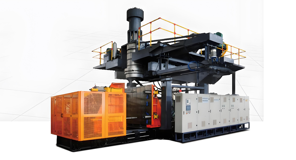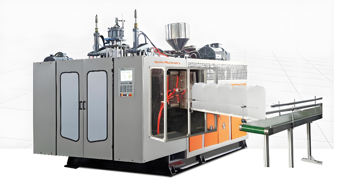
Introduction to EBM Machine Installation
Installing an Extrusion Blow Molding (EBM) machine is a critical phase that sets the stage for years of production. Unlike simpler machinery, EBM lines are complex systems involving heavy mechanical parts, high-voltage electronics, hydraulics, and compressed air systems. A proper installation ensures safety, optimal performance, and longevity of the equipment. While professional installation by the manufacturer is always recommended, understanding the process helps facility managers prepare the site and coordinate effectively with the engineering team. This guide provides a comprehensive, step-by-step overview for beginners, incorporating best practices from Apollo China’s global installation projects.
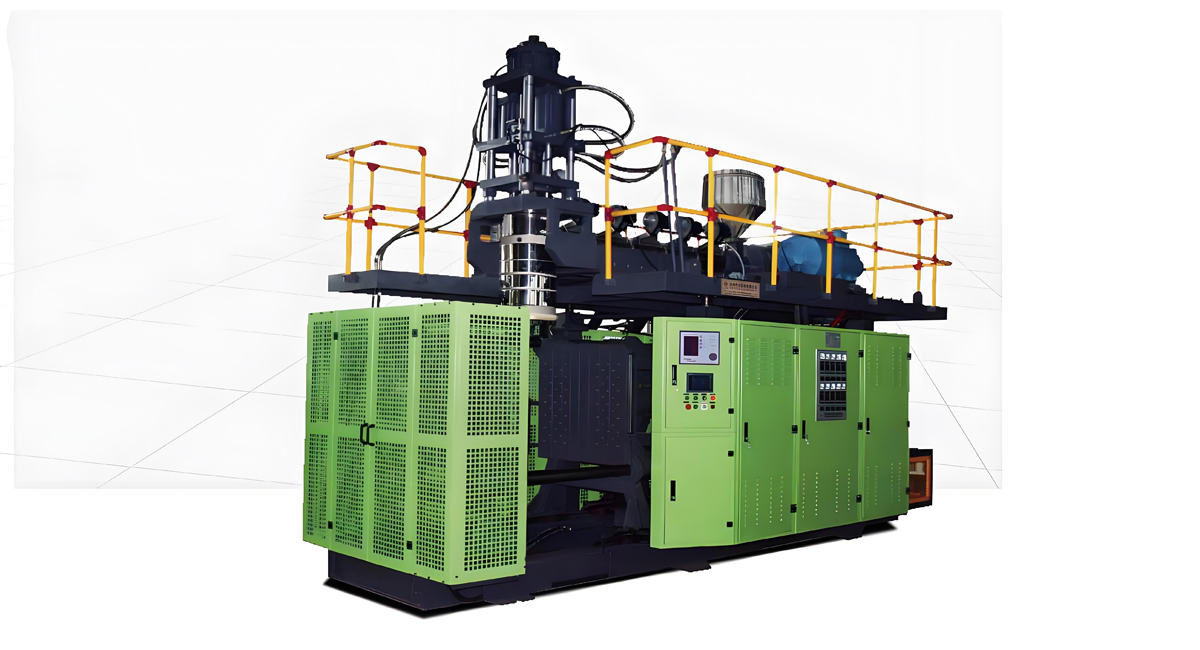
The installation process can be broken down into four main phases: Site Preparation and Foundation, Mechanical Assembly and Leveling, Electrical and Hydraulic Connection, and finally, Commissioning and Testing. Skipping or rushing any of these phases can lead to alignment issues, premature wear, or even catastrophic failure. At Apollo China, we provide a detailed installation manual and a dedicated supervision team to guide you through each step, ensuring your machine is up and running with minimal delay.
Phase 1: Site Preparation and Foundation
Before the machine arrives, your facility must be ready to receive it. This phase is often underestimated but is vital for stability.
Floor Load Capacity
EBM machines are incredibly heavy. A standard machine for 5-liter bottles can weigh between 5 to 10 tons, while large industrial machines for drums can exceed 20 tons. Your factory floor must have a load-bearing capacity that exceeds the machine’s weight by a safety factor of at least 1.5. For Apollo machines, we provide detailed foundation drawings specifying the weight distribution. If your floor is concrete, it should be at least 150mm thick and reinforced with steel mesh. For upper floors, structural engineering approval is mandatory.
Space and Layout Requirements
Allow sufficient space around the machine for operation and maintenance. A minimum of 1.5 meters of clearance is required at the rear for hydraulic connections and mold changes, and 2 meters at the front for operator access and material handling. Consider the layout of auxiliary equipment like hopper dryers, chillers, and air compressors. They should be placed as close as possible to the main machine to minimize energy loss and piping complexity. Apollo’s engineers can help design the cell layout to optimize material flow and reduce congestion.
Utility Connections
Ensure you have the correct power supply. Most EBM machines require 3-phase power (380V or 440V depending on the region) with a dedicated transformer. The voltage stability should be within plus or minus 5 percent to protect sensitive electronics. You will also need a compressed air supply with a minimum pressure of 0.6 MPa and a dew point below minus 20 degrees Celsius to prevent moisture in the pneumatic lines. Cooling water is another critical utility; it should be treated to prevent scaling in the heat exchangers. A soft water system or cooling tower is usually required.
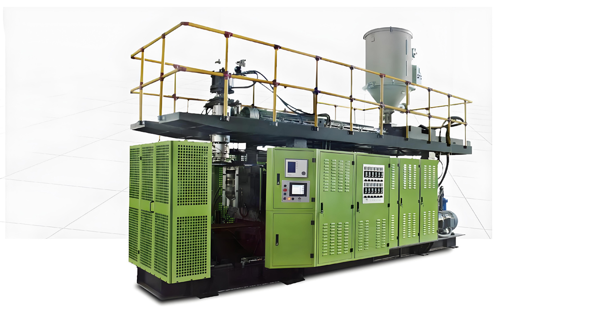
Phase 2: Mechanical Assembly and Leveling
Once the machine components arrive in crates, the assembly begins. This requires a crane or forklift with sufficient lifting capacity.
Unpacking and Handling
Carefully open the crates and inspect for any shipping damage. Use the lifting points indicated on the packaging. Never drag heavy components like the extruder barrel or clamping unit, as this can damage precision surfaces. Store the components in a clean, dry area. If assembly is delayed, apply anti-rust coating to machined surfaces.
Frame Assembly and Leveling
The machine frame (platen) is the foundation of the assembly. It must be placed on the foundation bolts or leveling pads. Use a precision spirit level (0.02mm/m accuracy) to ensure the frame is perfectly level in both longitudinal and transverse directions. Uneven leveling will cause the mold to not close properly, leading to flash (excess material) and damage to the mold edges. Shim the frame using steel wedges until perfect level is achieved, then tighten the anchor bolts and grout the base with non-shrink grout for permanent stability.
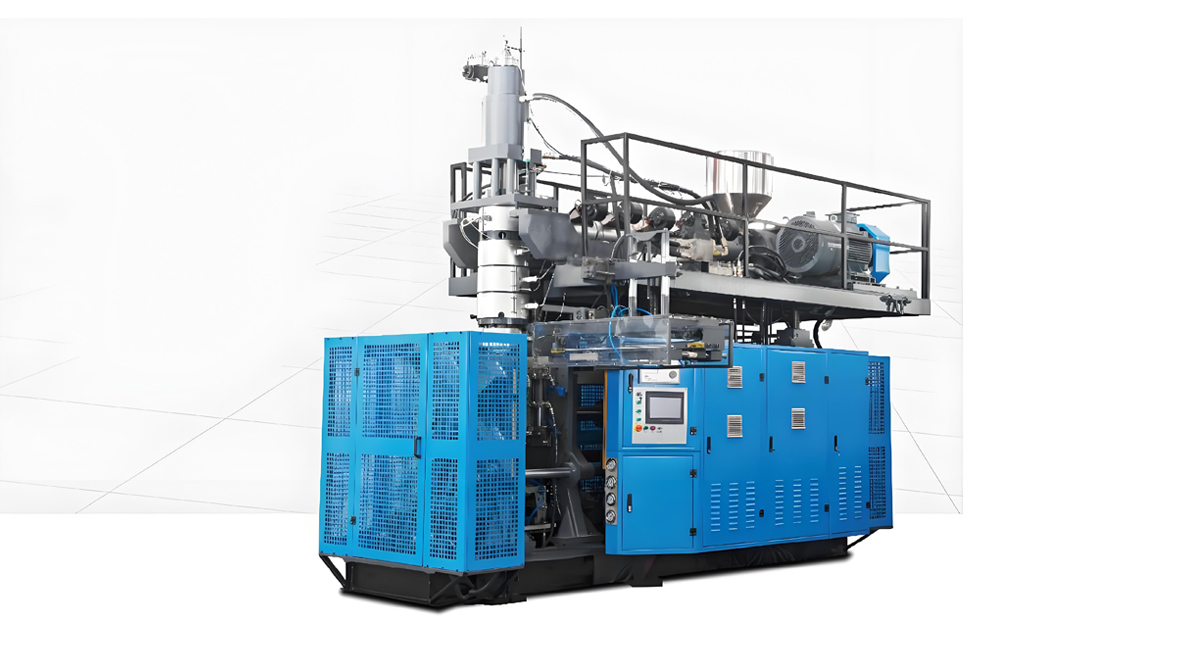
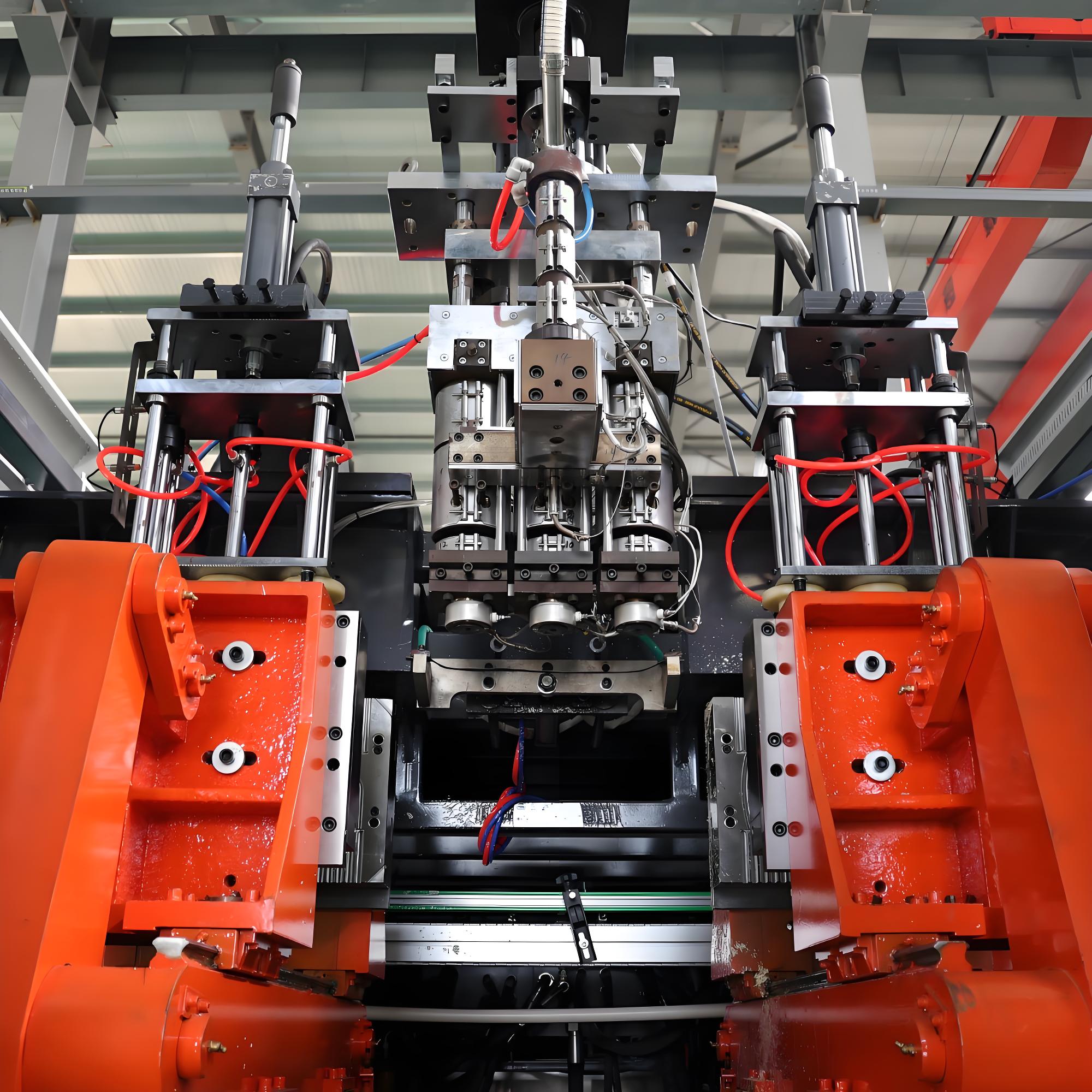
Installing the Extruder and Clamping Unit
The extruder is usually mounted on a sliding base for alignment adjustment. Lift the extruder and screw barrel assembly and bolt it to the frame. Next, install the clamping unit (toggle or hydraulic). The critical step here is aligning the extruder center with the die head and the mold center. Even a millimeter of misalignment can cause parison thickness variation. Apollo machines come with laser alignment tools or precision boring to ensure co-axiality, but final adjustment is done on-site using dial indicators.
Die Head and Blowing Mechanism
Install the die head onto the extruder flange. Ensure the sealing surface is clean and free of nicks. Tighten the connecting bolts in a star pattern to ensure even pressure. Install the blowing core (mandrel) and the blowing air rings. These components must move freely without binding. For accumulator head machines, install the hydraulic accumulator and piping, ensuring there are no leaks in the high-pressure lines.
Phase 3: Electrical and Hydraulic Wiring
This phase requires certified electricians and fitters. Always follow local safety codes and lock-out/tag-out procedures.
Hydraulic System Installation
Install the hydraulic power unit (pump, motor, tank, and valve block) in a location with good ventilation. Connect the hydraulic hoses to the machine’s actuators (clamping cylinder, extruder drive, accumulator). Use the correct torque values on fittings to prevent stripping. Before energizing the pump, flush the system with cleaning oil to remove debris from the pipes. Fill the tank with the recommended grade of hydraulic oil (typically ISO 46 or 68 anti-wear hydraulic oil). Bleed the air from the cylinders by loosening the bleed screws and running the cylinders through full strokes.
Electrical Wiring and Grounding
Connect the main power cable to the control cabinet. Ensure proper grounding (earthing) of the machine frame to prevent electrical shock and interference. Wire the motors, heaters, and sensors to the PLC terminals according to the wiring diagram. Use ferrules on wire ends for reliability. Install the temperature controllers and verify that the thermocouple types (J or K) match the controller settings. For the control system, connect the HMI (touch screen) and test the communication between the PLC and the inverters/servos.
Cooling and Air Systems
Connect the water chiller to the mold cooling channels and the barrel cooling jacket. Pressure test the water lines to check for leaks. Install the high-pressure air compressor line to the blowing station, including the filter, regulator, and lubricator (FRL) unit. Install the low-pressure air line for pneumatic cylinders. Ensure all air lines are color-coded or labeled to avoid confusion during maintenance.
Phase 4: Commissioning and Testing
Commissioning is where the machine comes to life. It must be done methodically to avoid damage.
Initial Checks
Before turning on the power, manually rotate the screw by hand (if possible) to ensure it turns freely without grinding. Check all safety interlocks, such as emergency stop buttons and safety gates. Verify that the direction of rotation for the motors is correct (forward only for the extruder). Incorrect rotation can destroy the screw and barrel in seconds.
Heating and Thermal Stabilization
Power up the heaters. Set the barrel and die head temperatures to the material specifications (e.g., 180-220 degrees Celsius for HDPE). Allow the machine to soak for at least 2 hours to ensure thermal expansion has stabilized. Check for any cold spots using an infrared thermometer. Tighten the heater bands again after the first heat-up, as thermal expansion can loosen them.
Material Loading and Purging
Load the plastic resin into the hopper. Start the extruder at a very low speed (5-10 RPM). Do not apply backpressure yet. Allow the material to melt and push out any residue or cleaning compound from the barrel. This is known as purging. Once the melt is clean and consistent, gradually increase the speed and backpressure.
Mold Closing and Parison Programming
With the extruder running, perform a dry cycle (without air blow) to test the mold closing mechanism. Ensure the mold locks securely and the clamping pressure is set correctly. Adjust the parison programmer (if equipped) to control the wall thickness distribution. This involves setting the gap between the die lips and the mandrel at different heights to create a specific bottle wall profile.
First Article and Tuning
Introduce compressed air to blow the first bottle. This “first article” will likely be imperfect. Adjust the blow pressure, cycle time, and cooling time. Measure the bottle weight and wall thickness using a micrometer or ultrasonic gauge. Iterate the settings until the bottle meets the specifications. Apollo engineers typically stay on-site for 3-5 days to fine-tune the machine and train operators on these adjustments.
Safety Precautions During Installation
Safety is paramount. Always wear PPE (hard hat, safety shoes, gloves). Secure heavy loads with chains or straps during lifting. Isolate energy sources (lock-out/tag-out) before working on electrical or hydraulic systems. Ensure fire extinguishers are nearby, as heating plastic carries a fire risk. Apollo China provides a comprehensive safety manual and conducts a safety briefing before any installation work begins.
Troubleshooting Common Installation Issues
Beginners often encounter issues like hydraulic leaks (usually due to over-tightened fittings), heater burnout (due to voltage mismatch), or misaligned molds. If the machine vibrates excessively, check the foundation bolts and leveling. If the parison sags unevenly, check the centering of the die head. Keeping a log of all adjustments during installation is crucial for future maintenance. Apollo China’s remote support team can analyze these logs to provide precise troubleshooting advice.
Conclusion
Proper installation of an Extrusion Blow Molding machine is a complex but manageable process with the right preparation and guidance. By following this step-by-step guide and leveraging the expertise of manufacturers like Apollo China, you can ensure a smooth setup that maximizes machine uptime and product quality. Remember, a well-installed machine is a productive machine. For professional installation support and high-quality EBM equipment, contact Apollo China at www apollo-china.com. Our team is ready to assist you from foundation design to the first successful bottle production.