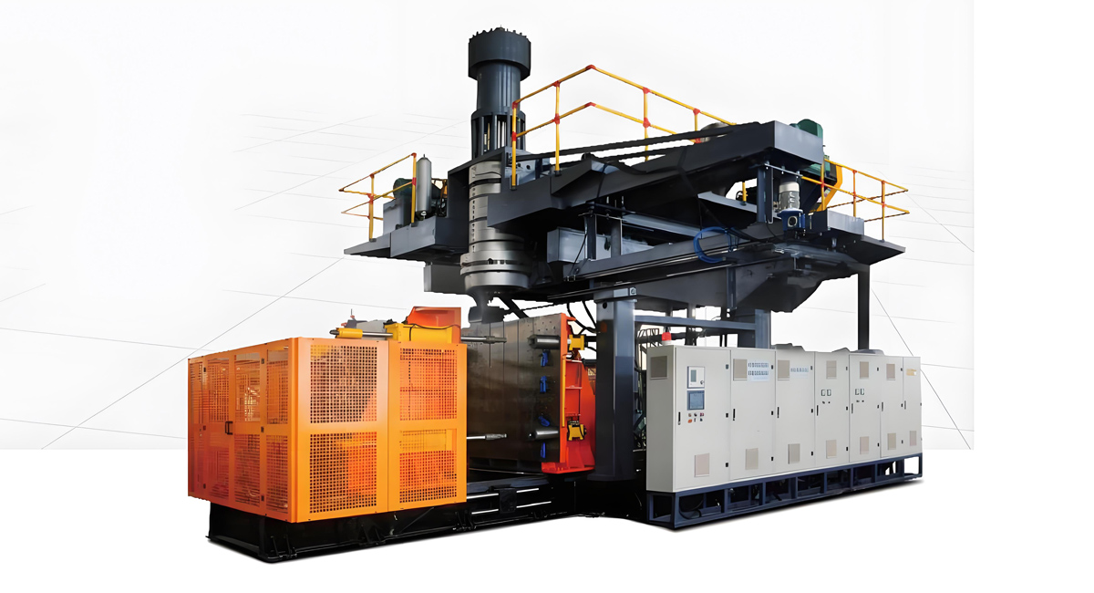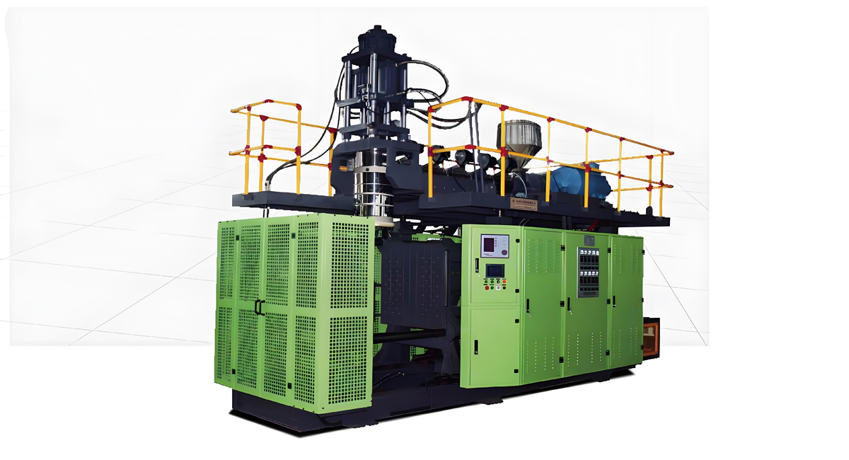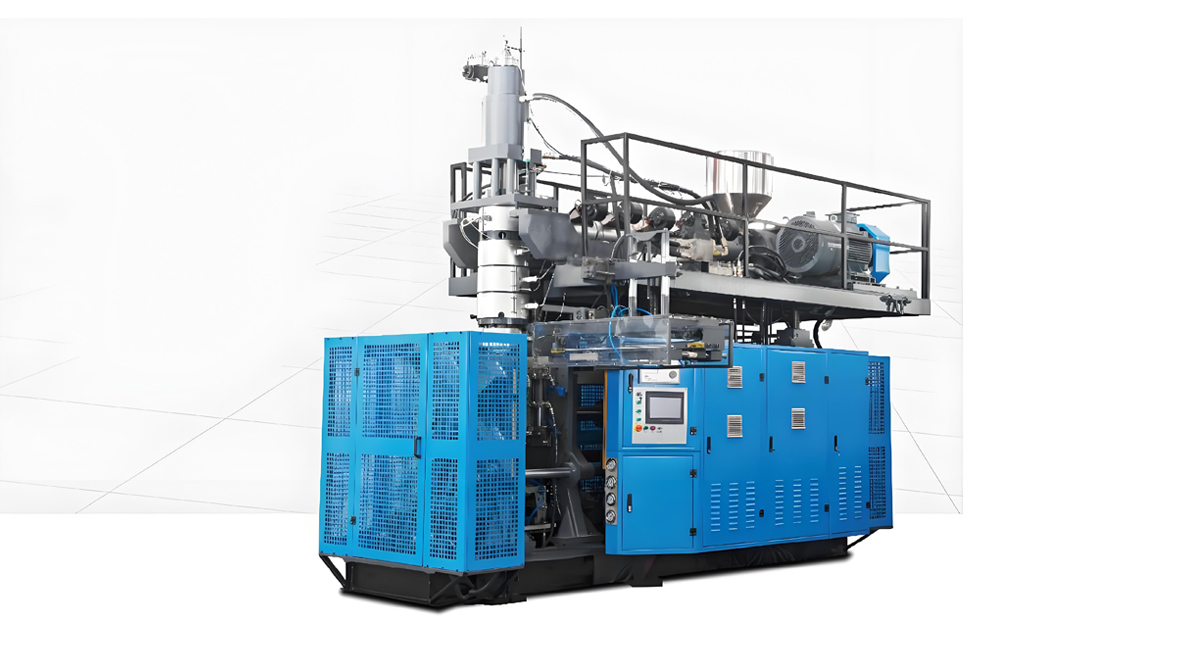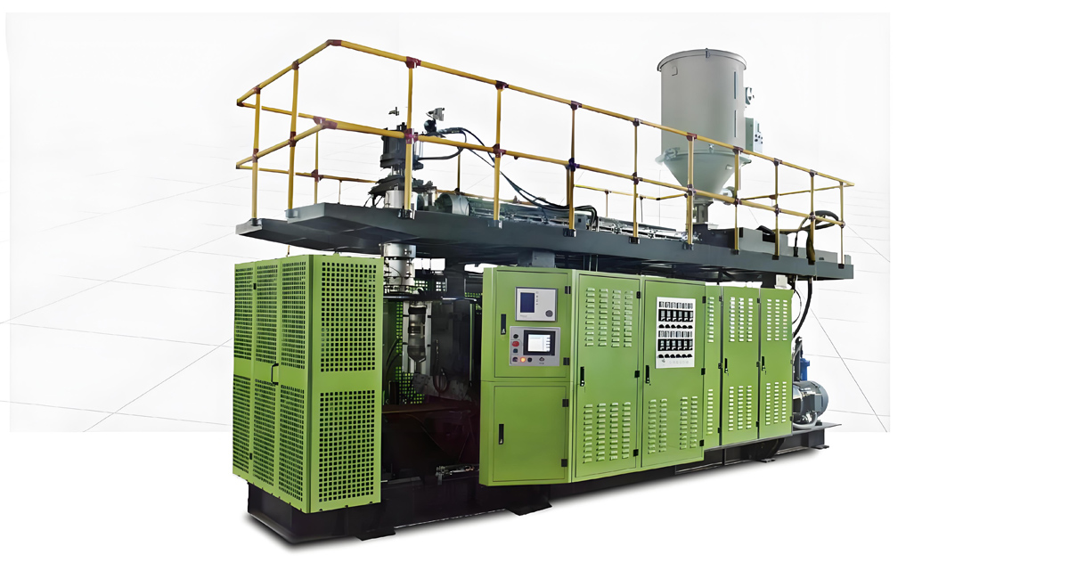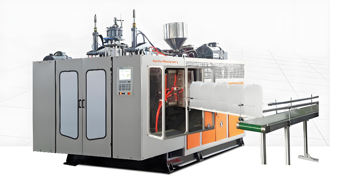

As the core equipment for the production of hollow plastic products, extrusion blow molding machines realize the transformation of thermoplastic materials such as polyethylene, polypropylene, and polyvinyl chloride into various hollow products through a continuous process of “raw material plasticization – parison extrusion – mold clamping and locking – blow molding – cooling and demolding”. Their structural design must ensure melt plasticization uniformity, parison dimensional accuracy, molding stability, and production efficiency. They are mainly composed of three core units: the extrusion system, clamping system, and blow molding system, as well as a control system and auxiliary devices. All units cooperate synergistically to form a complete production closed loop. The following is a detailed analysis of the composition, functions, and key technical points of each structural module.
I. Core Power Unit: Extrusion System
The extrusion system is the “power heart” of the extrusion blow molding machine. Its core function is to convert solid plastic pellets into uniformly molten melt and continuously and stably extrude them to form a tubular parison. The performance of this system directly determines the melt quality, which in turn affects the mechanical properties and appearance accuracy of the products. It is mainly composed of a screw and barrel, heating and cooling devices, a transmission device, and a feeding device.
1. Screw and Barrel: Core Plasticizing Components
The matching accuracy of the screw and barrel is crucial to the plasticizing effect, and the two form a closed material conveying and melting space. As the core moving component, the screw is divided into two structures according to the characteristics of the processed materials: the gradual change type and the sudden change type. The gradual change type screw is suitable for crystalline plastics such as polyethylene, realizing stable melting through the slow change of the screw groove depth; the sudden change type screw is suitable for non-crystalline plastics such as polyvinyl chloride, enhancing shear heating through the sudden change of the screw groove depth to improve melting efficiency. In industrial applications, the screw length-diameter ratio (ratio of effective length to diameter) is usually controlled between 20:1 and 30:1, and the compression ratio (ratio of the groove depth of the feeding section to the metering section) is 2.5:1 to 4:1. For example, when processing high-density polyethylene (HDPE), selecting a screw with a length-diameter ratio of 28:1 and a compression ratio of 3.5:1 can improve the melt uniformity by 15%.
The barrel is a high-strength metal cylinder, and its inner wall is nitrided or sprayed. The hardness must reach above HV900 to resist material wear. The gap between the barrel and the screw is controlled within the range of 0.1-0.3mm to ensure material conveying efficiency and shearing effect.
2. Heating and Cooling Devices: Precise Temperature Control Guarantee
To achieve gradual melting and stable plasticization of materials, the outer part of the barrel is heated by segmented electric heating coils with a power density of 1.5-3.0W/cm², usually divided into 3-5 segments for independent temperature control. The temperature of different processing stages must be accurately matched with the material characteristics. For example, when processing polypropylene (PP), the temperature of the feeding section is controlled at 160-180℃, the compression section at 180-200℃, and the metering section at 200-220℃. The temperature fluctuation must be strictly controlled within ±2℃ to avoid melt overheating decomposition or poor plasticization.
The cooling system cooperates with the heating device to achieve temperature balance, usually adopting air cooling or water cooling. The water temperature must be controlled below 30℃. Its main function is to cool the materials in the feeding section to prevent premature melting leading to unsmooth feeding. At the same time, it can adjust the temperature accuracy of each section of the barrel to ensure stable melt performance.
3. Transmission and Feeding Devices: Power and Feeding Guarantee
The transmission device is composed of a frequency conversion motor, a reducer, and a coupling, providing stable power for the screw rotation. The motor power is matched according to the screw diameter. For example, a Φ65mm screw is usually equipped with a 30-45kW frequency conversion motor, and the speed adjustment range is 10-100r/min. The precise adjustment of the extrusion volume can be achieved through frequency conversion control. The reducer ratio is generally 10:1 to 20:1. The alignment accuracy of the coupling must be regularly checked to ensure that the radial deviation is ≤0.1mm and the end face deviation is ≤0.05mm, so as to avoid screw wear caused by transmission vibration.
The feeding device is centered on a hopper, equipped with an automatic suction machine to achieve continuous feeding. The conveying capacity is 500-2000kg/h, and the hopper volume is usually 50-200L. For moisture-absorbing materials such as nylon, a dryer must be matched. The drying temperature is 80-120℃, and the drying time is 4-6 hours to ensure that the moisture content of the raw materials is ≤0.1%, avoiding bubbles in the melt that affect product quality.
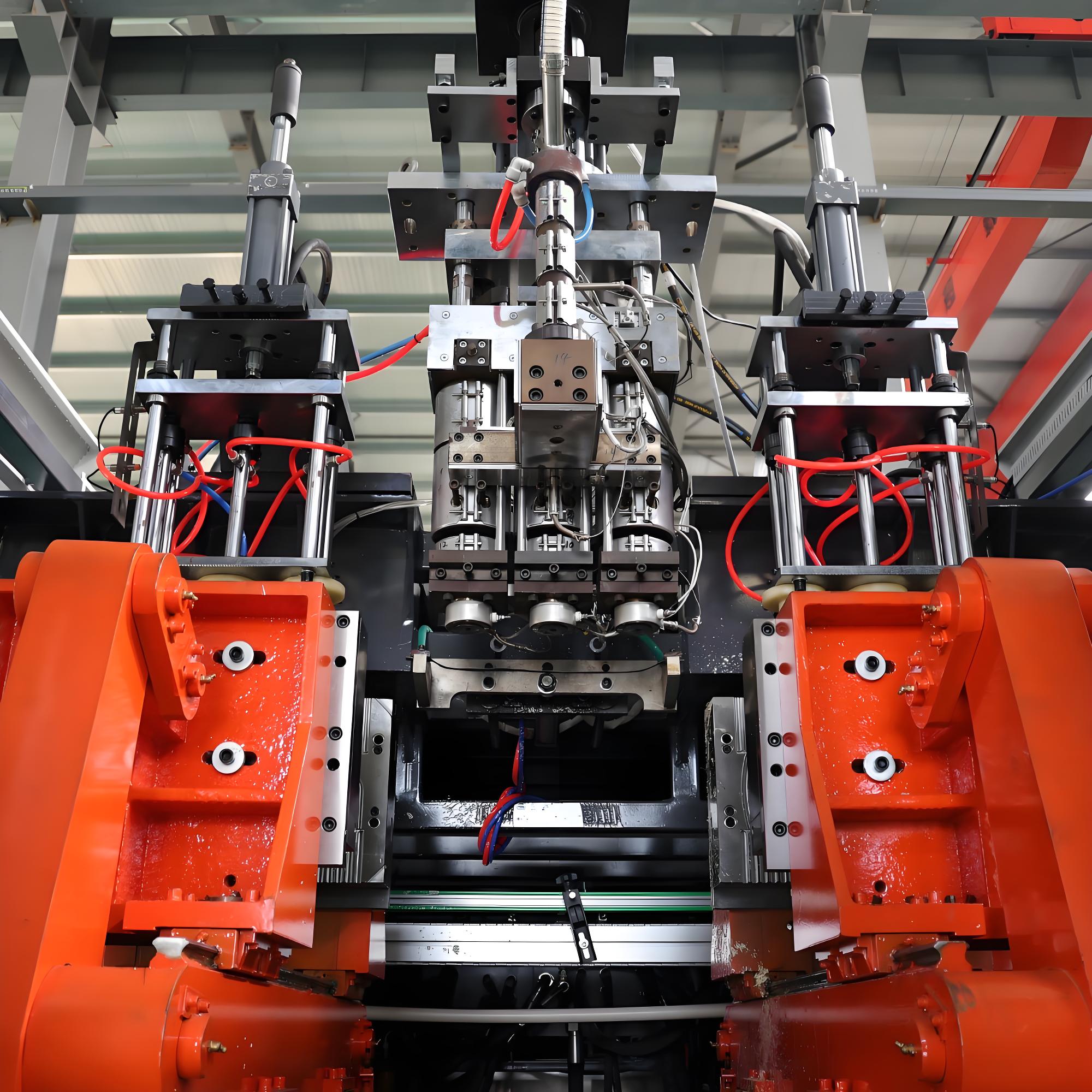
II. Molding Accuracy Guarantee Unit: Clamping System
The clamping system is responsible for the functions of mold closing, locking, opening, and product demolding. Its stability directly affects product dimensional accuracy, mold life, and production safety. It is mainly composed of templates and guide pillars, a mold clamping mechanism, and safety protection devices.
1. Templates and Guide Pillars: Guiding and Positioning Foundation
The moving template and fixed template are the carriers for mold installation, usually made of Q235 or 45 steel with a thickness of 200-500mm, and realize precise guiding and connection through guide pillars. The guide pillar diameter is Φ50-150mm, the length is 1000-3000mm, the straightness requirement is ≤0.02mm/m, and the surface hardness is HRC50-55, ensuring that the template movement parallelism is ≤0.1mm/m to avoid product flash or dimensional deviation caused by mold misalignment during clamping. In practical applications, the guide pillars must be regularly lubricated with high-temperature lithium-based grease, once every 200 hours, to prevent surface scratches caused by dry friction.
2. Mold Clamping Mechanism: Core Locking Power
The core function of the mold clamping mechanism is to provide sufficient clamping force to resist the spreading force of compressed air on the mold during the blow molding process, ensuring that the mold is tightly closed. Industrially, hydraulic or mechanical-hydraulic composite (toggle-type) mold clamping mechanisms are mainly used: Hydraulic mold clamping provides power through an oil cylinder with a diameter of Φ100-300mm, and the working pressure is 16-25MPa. The clamping force calculation follows the formula “Clamping force = Product projected area × Unit area clamping force”, and the unit area clamping force is generally 3-5 tons/square meter; Toggle-type mold clamping amplifies the hydraulic thrust by 3-5 times through a connecting rod mechanism, which can save energy consumption by 20%-30%, but the toggle joint gap must be regularly checked to be ≤0.2mm to avoid loose mold clamping.
3. Safety Protection Devices: Key to Production Protection
To ensure the safety of equipment and operators, the clamping system is equipped with multiple protection devices: The mold protector detects whether there are foreign objects before mold closing through an infrared sensor, avoiding equipment damage caused by metal fragments and other debris being stuck in the mold; The hydraulic overload protection is realized by a pressure relay, and the set value is 110% of the maximum clamping force to prevent mechanism deformation caused by overload. An enterprise once suffered a direct loss of about 80,000 yuan due to mold damage because the mold protector was not activated, highlighting the necessity of protection devices.
III. Molding Execution Unit: Blow Molding System
The blow molding system is the core unit that transforms the tubular parison into the target product shape. By introducing compressed air into the parison, the melt expands and closely fits the inner wall of the mold, and forms a hollow product after cooling and setting. It is mainly composed of a blow pin, an air circuit control device, and a mold exhaust structure.
1. Blow Pin: Core of Gas Introduction
The blow pin is a hollow steel tube structure with an outer diameter of Φ5-20mm and a wall thickness of 1-3mm. The head is conical at 30°-60°, which is convenient for smooth insertion into the parison and avoiding piercing the melt. The blow pin must be accurately aligned with the center of the parison, with a deviation of ≤1mm, and the insertion depth is 1/3-1/2 of the parison length. For example, when the parison length is 300mm, the insertion depth is controlled at 100-150mm. Too shallow insertion may lead to unblown product top, and too deep insertion may damage the parison.
2. Air Circuit Control Device: Stable Blow Molding Guarantee
The air circuit system is responsible for providing stable compressed air. The core components include an air compressor, an air storage tank, a solenoid valve, and a pressure sensor. The air compressor displacement is 0.5-5m³/min, and the working pressure is 0.8-1.2MPa; The air storage tank volume is 0.5-2m³, used to stabilize the air source pressure and avoid pressure fluctuations during the blow molding process; The solenoid valve response time is ≤50ms to ensure precise control of the blowing timing; The pressure sensor accuracy is ±0.01MPa, real-time monitoring the blowing pressure.
The blowing parameters must be adjusted according to the material characteristics: The blowing pressure for polyethylene (PE) products is 0.3-0.6MPa, and for polycarbonate (PC) products is 0.8-1.0MPa; The blowing time changes with the product wall thickness, about 3 seconds for a wall thickness of 2mm and 8 seconds for 5mm, ensuring that the product is fully expanded and the wall thickness is uniform.
3. Mold Exhaust Structure: Appearance Quality Guarantee
The mold cavity must be provided with uniformly distributed exhaust holes with a diameter of Φ0.5-1.0mm and a spacing of 5-10mm, used to discharge the air inside the cavity during the parison expansion process, avoiding product surface depressions caused by air retention. At the same time, the blowing port position must avoid the product ribs or thread structures to prevent deformation caused by excessive local pressure.
IV. Central Control Unit: Control System
The control system is the “brain” of the extrusion blow molding machine, responsible for coordinating the collaborative work of various systems, realizing precise control of process parameters such as temperature, pressure, speed, and time, and ensuring the stability and repeatability of the production process. It is mainly composed of an electrical control unit, a human-machine interface, and executive components.
1. Precision Control Module: Core Regulation Function
Temperature control adopts a PID (Proportional-Integral-Derivative) controller to perform segmented temperature control on the extruder barrel, mold, and other parts. Each segment is equipped with a thermal resistance sensor with an accuracy of ±0.5℃, and the heating coil power is adjusted through a solid-state relay, with a temperature control accuracy of ±1℃; The hydraulic system pressure is controlled by a proportional valve with an adjustment accuracy of ±0.5MPa. The clamping speed adopts a three-stage control of “slow-fast-slow”, with a low speed of ≤5mm/s and a high speed of 50-100mm/s to avoid mold collision; The blow molding air circuit pressure is adjusted through an electro-pneumatic proportional valve, and the pressure stabilization time is ≤0.1 seconds to ensure uniform parison expansion.
2. Human-Machine Interface and Fault Monitoring: Operation and Protection Guarantee
The human-machine interface usually adopts a 7-15 inch touch screen. Operators can set process parameters such as extrusion speed, clamping force, and blowing time, and real-time view production status data such as temperature curves and pressure values. The system has a complete fault alarm function, which can timely alarm and shut down the machine for abnormal conditions such as over-temperature, under-pressure, and mold foreign objects, and record fault information for easy troubleshooting. Operation authority implements hierarchical management. Ordinary operators can only modify process parameters, and administrators can adjust the control program to prevent misoperation.
V. Production Guarantee Unit: Auxiliary Devices
Although auxiliary devices do not directly participate in the core molding process, they are crucial to production continuity, product quality, and environmental protection. They mainly include a cooling system, a demolding device, a scrap edge treatment device, and a raw material pretreatment device.
The cooling system is divided into mold cooling and product cooling: Mold cooling adopts 20-30℃ circulating water, and the water pipes are arranged near the cavity with a distance of ≤10mm to ensure that the mold surface temperature difference is ≤5℃; Product cooling can be achieved through in-mold delayed blowing (pressure 0.2-0.4MPa, delay 0.5-2 seconds) or out-of-mold air cooling (wind speed 5-10m/s), which can shorten the molding cycle by 20%-30%. The demolding device is mostly a robotic arm or an ejection cylinder with an ejection force of 5-50kN. The ejection position avoids weak parts of the product (such as threads and sharp corners) to prevent product damage. The scrap edge treatment device is composed of an automatic cutter and a crusher. The cutter edge hardness is HRC55-60, and the gap with the mold is ≤0.1mm to ensure clean scrap edge cutting. The particle size of the crushed particles is 2-5mm, which can be recycled and reused, but the recycling ratio does not exceed 30% to avoid affecting product performance.
VI. Summary of Structural Coordination and Performance Optimization
The structural composition of extrusion blow molding machines presents the characteristics of “multi-system collaboration and high-precision matching”: The extrusion system ensures melt uniformity, the clamping system ensures molding accuracy, the blow molding system realizes shape formation, the control system coordinates overall, and the auxiliary devices ensure continuous production. The parameter matching of each system directly determines production efficiency and product quality, such as the matching of the screw length-diameter ratio with material plasticization requirements, the matching of clamping force with product projected area, and the matching of blowing pressure with material fluidity.
With the development of intelligent manufacturing technology, the structural design of modern extrusion blow molding machines is gradually upgrading towards “precision, automation, and energy saving”: improving plasticization efficiency by optimizing the screw and barrel structure, reducing energy consumption by adopting toggle-type mold clamping mechanisms, and introducing intelligent monitoring systems to realize real-time optimization of process parameters. In the future, with the integration of polymer material technology and equipment manufacturing technology, the structure of extrusion blow molding machines will further adapt to the production needs of complex products such as multi-material co-extrusion, thin-walled, and large-scale, promoting the high-quality development of the hollow plastic product industry.