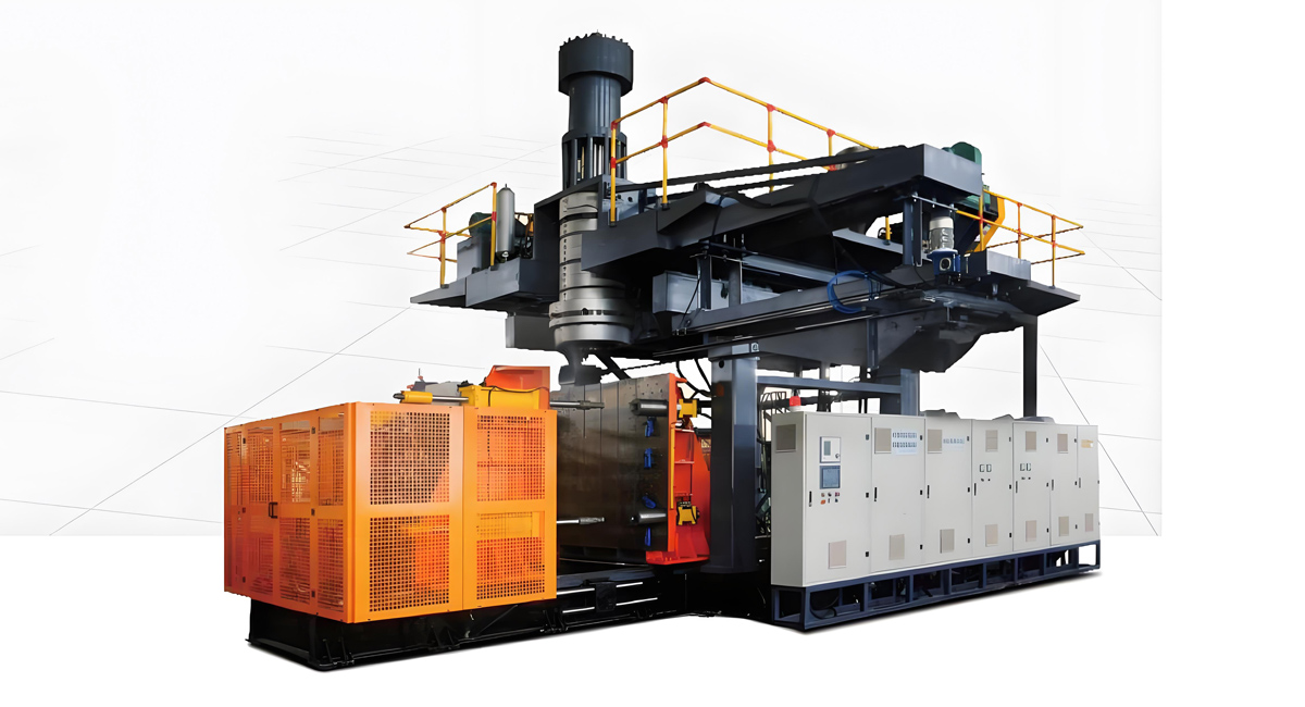
Installing an extrusion blow molding machine represents a significant milestone for manufacturers entering the plastic container production industry. Proper installation is critical for ensuring optimal machine performance, production quality, and long-term reliability. This comprehensive guide provides detailed step-by-step instructions for installing extrusion blow molding machines, with specific considerations for Apollo equipment, helping beginners navigate the installation process with confidence and minimize startup challenges. The installation process involves multiple phases including site preparation, equipment delivery, machine positioning, utility connections, calibration, and testing, each requiring careful attention to detail and adherence to manufacturer specifications.
Proper installation of extrusion blow molding machines directly impacts production efficiency, product quality, and operational costs. Poorly installed machines may experience increased maintenance requirements, reduced production capacity, quality inconsistencies, and safety hazards. The installation investment typically ranges from $5,000 to $15,000 including professional services, but this investment pays dividends through reduced startup problems and optimized performance throughout the equipment lifespan. This guide covers all essential aspects of installation from initial site planning through final production startup, providing practical guidance for both technical personnel and facility managers overseeing the installation process.
Pre-Installation Planning and Site Preparation
Thorough pre-installation planning and site preparation lay the foundation for successful equipment installation and long-term operational success. This phase involves comprehensive assessment of facility conditions, utility infrastructure, and operational requirements, ensuring that the installation site meets all specifications before equipment delivery. The planning process should begin 6-8 weeks before expected equipment arrival, providing adequate time for any necessary facility modifications or infrastructure upgrades.
Site Location Assessment
Selecting the optimal location for extrusion blow molding equipment requires evaluation of multiple factors including floor space availability, ceiling height, structural load capacity, proximity to supporting operations, and workflow efficiency. The typical Apollo extrusion blow molding machine requires floor space ranging from 200-600 square feet depending on machine size and configuration, with additional space required for material handling, finished product storage, and operator access. Ceiling height requirements typically range from 12-16 feet to accommodate equipment height and allow for maintenance access. Structural floor load capacity should exceed 500 pounds per square foot for most machines, with larger capacity machines requiring reinforced flooring capable of supporting 800-1000 pounds per square foot.
Site selection should also consider proximity to material storage areas, which typically require 500-2000 square feet depending on production volume and material types. Finished product storage areas should be positioned for efficient material flow, minimizing travel distance and handling between machine and storage. The location should also provide adequate ventilation for heat dissipation from machine operation, with ventilation systems capable of handling 2000-5000 CFM depending on machine size. Lighting requirements include general illumination of 300-500 lux for safety and production areas, with task lighting of 500-750 lux for maintenance and inspection activities.
Utility Infrastructure Verification
Utility infrastructure verification is essential for ensuring that facility capabilities match equipment requirements. Electrical requirements for extrusion blow molding machines typically include three-phase power with voltage ranges of 380-480V and amperage ranging from 100-400 amps depending on machine size and configuration. Power consumption ranges from 50-200 kW for typical machines, requiring appropriately sized main circuit breakers and power distribution panels. Electrical infrastructure should include ground fault protection, surge protection, and emergency stop capabilities integrated with the machine control system.
Air supply requirements typically include compressed air at 80-120 PSI with flow rates ranging from 20-100 CFM depending on machine size and configuration. Air systems should include filtration, moisture removal, and oil-free compressed air to prevent contamination of plastic products. The air system should provide consistent pressure with minimal variation, as pressure fluctuations can significantly impact product quality and consistency. Water cooling requirements include flow rates of 5-30 gallons per minute at 15-25 PSI, depending on machine size and cooling requirements. The water system should include filtration to prevent scaling and cooling tower or chiller capacity to maintain water temperature below 25°C during continuous operation.
Foundation and Floor Preparation
Proper foundation and floor preparation are critical for machine stability, vibration reduction, and precision operation. The foundation should provide a flat, level surface with tolerance of plus or minus 0.02 inches per foot. Concrete floors should have minimum 28-day compressive strength of 3000 PSI, with 4000 PSI recommended for larger machines. Floor surface finish should provide good traction while being smooth enough to allow equipment movement and operator safety. Expansion joints or isolation pads should be considered between machine foundations and surrounding floors to prevent vibration transmission to adjacent equipment or structures.
Machine footings should be designed based on equipment weight and dynamic loads, with typical footing depths ranging from 12-24 inches for most machines. Foundation anchors should be installed per equipment specifications, with typical anchor bolt sizes ranging from M16-M24 depending on machine size. The foundation design should include drainage channels for cooling water overflow and cleaning operations. Floor coatings should be chemical resistant to withstand cleaning chemicals and potential plastic material spills. Foundation preparation typically costs $2,000-8,000 depending on site conditions and machine size, but represents a critical investment in long-term operational stability and product quality.
Equipment Delivery and Unloading Procedures
Proper handling of equipment during delivery and unloading prevents damage and ensures safe installation. Extrusion blow molding machines are substantial pieces of equipment weighing anywhere from 8,000 to 50,000 pounds depending on size and configuration, requiring specialized handling equipment and procedures. The delivery phase begins with equipment packaging and transportation from the manufacturing facility to the installation site, followed by careful unloading and positioning within the installation area.
Shipping Preparation and Transportation
Apollo extrusion blow molding machines are packaged for international shipping in robust wooden crates designed to withstand ocean transport and handling during loading and unloading operations. The packaging typically includes moisture barrier materials, shock protection, and securing systems to prevent movement during transit. Shipping documentation includes detailed packing lists identifying all components and accessories, with individual item numbering to facilitate inspection and identification during unpacking. Equipment typically ships in multiple containers or crates depending on machine size, with the main machine body, control system, and major accessories packaged separately.
Transportation costs typically range from $3,000 to $12,000 depending on equipment size, shipping distance, and logistics requirements. Ocean freight typically takes 4-6 weeks from China to major international ports, with additional time for inland transportation to the installation site. Shipping insurance typically costs 0.5-1.0% of equipment value and provides protection against damage or loss during transit. The equipment should be inspected upon arrival for any shipping damage, with detailed documentation and photographs taken of any issues for insurance claims. Working with experienced freight forwarders and logistics providers familiar with industrial equipment shipping helps ensure smooth delivery and minimizes the risk of damage or delays.
Unloading Equipment and Positioning
Unloading extrusion blow molding equipment requires appropriate lifting equipment including forklifts with adequate capacity, cranes, or gantry systems depending on installation site access and equipment size. Forklift capacity should be at least 1.5 times the weight of the heaviest component being lifted, with typical requirements ranging from 12,000 to 75,000 pound capacity depending on machine size. Lifting slings and rigging equipment should be rated for at least 1.5 times the component weight and should be inspected before each use for wear or damage. The lifting plan should identify appropriate lifting points as specified by the manufacturer, with consideration given to center of gravity and balance during lifting operations.
Equipment positioning requires careful planning to ensure proper alignment with other equipment and facility infrastructure. The machine should be positioned according to the installation layout plan, with consideration given to maintenance access, operator workflow, and material handling requirements. Precise positioning is critical for utility connections, with electrical panels, air connections, and water cooling connections typically positioned at specific locations on the machine. Positioning accuracy requirements typically range from plus or minus 0.05 inches for major machine components to ensure proper alignment and prevent stress on machine structure. The machine should be leveled using precision leveling equipment, with tolerance requirements of plus or minus 0.02 inches per foot.
Protective Packaging Removal and Component Inspection
Protective packaging should be removed systematically and carefully to prevent damage to machine components or surfaces. The unpacking process should begin with documentation of the packaging condition and any visible damage. Packaging should be removed in the reverse order of installation, with outer protective materials removed first, then intermediate protection, and finally internal protective coverings. All protective materials should be carefully removed and stored for potential use during future transport or maintenance operations. Detailed inspection should be conducted as components are uncovered, with particular attention to precision surfaces, electrical components, and moving parts.
A comprehensive inspection checklist should be completed during the unpacking process, documenting the condition of each component and identifying any damage, missing parts, or discrepancies from the packing list. Digital photographs should be taken of each major component for documentation and future reference. Any damage or missing parts should be documented immediately and reported to the manufacturer for resolution. The inspection process typically takes 4-8 hours for standard machines and 12-24 hours for large capacity or complex machines. This inspection process is critical for preventing installation delays and ensuring that all required components are available before beginning the installation process.
Machine Assembly and Installation
Machine assembly and installation transforms the delivered components into a functioning production system ready for operation. This phase requires careful attention to detail, adherence to manufacturer specifications, and systematic completion of assembly tasks in the proper sequence. The assembly process varies significantly depending on machine size and configuration, with some machines arriving largely pre-assembled while others require extensive on-site assembly.
Main Machine Body Installation
The main machine body installation begins with positioning the machine foundation or leveling feet according to the installation diagram. Machine leveling is critical for proper operation, with precision leveling equipment including digital levels and laser alignment tools recommended for accuracy. The machine should be leveled in multiple directions with tolerance of plus or minus 0.02 inches per foot. Once leveled, the machine should be anchored to the foundation using appropriate anchor bolts specified by the manufacturer, with anchor bolt tightening torques ranging from 150-400 ft-lbs depending on bolt size and machine requirements.
Machine frame alignment ensures that all major components are properly positioned relative to each other. Alignment checks should include verification of parallelism between extruder and mold stations, perpendicularity between platen surfaces and machine centerline, and proper spacing between major assemblies. Alignment tools including dial indicators, laser alignment systems, and precision measuring equipment are typically required. Alignment tolerance requirements typically range from 0.001 to 0.003 inches depending on the specific component and machine size. Proper alignment is essential for preventing premature wear, ensuring product quality, and achieving maximum production efficiency.
Extruder System Assembly
The extruder system assembly includes installation of the barrel, screw, and drive system for machines where these components are not pre-installed. The barrel should be installed according to manufacturer specifications, with attention to barrel heating zones alignment and electrical connections. The screw assembly typically requires careful handling to prevent damage to screw flights or barrel surfaces. Screw-barrel clearance should be verified using appropriate measuring techniques, with clearances typically ranging from 0.003 to 0.008 inches depending on machine size and application requirements.
The drive system assembly includes motor installation, coupling alignment, and power transmission components. Motor mounting should ensure proper alignment with gearboxes or direct drive systems, with coupling alignment tolerances typically ranging from 0.001 to 0.002 inches depending on coupling type. Power transmission components including belts, pulleys, or gears should be installed with proper tension and alignment. The extruder system typically represents 30-40% of total machine cost, with installation costs for this subsystem ranging from $1,000-3,000 for professional assembly. Proper extruder installation is critical for material melting, homogenization, and consistent parison formation.
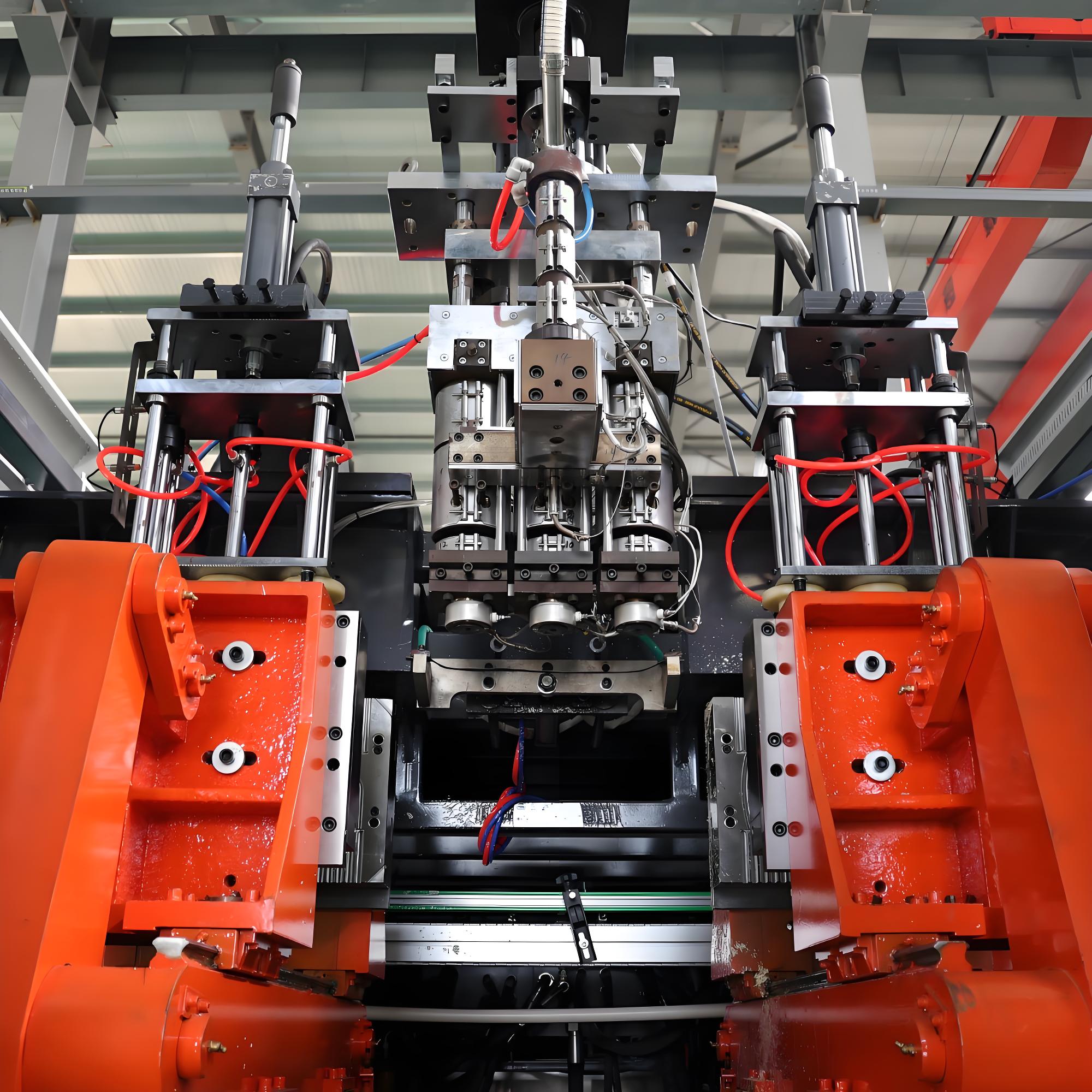
Blow Mold and Clamping System Installation
The blow mold and clamping system installation represents another critical installation phase requiring precision and attention to detail. The mold mounting surfaces should be cleaned and inspected for damage before installation. Molds should be installed according to manufacturer specifications, with attention to proper alignment, secure mounting, and adequate clearance for mold movement. Mold alignment is critical for product quality and tooling longevity, with alignment requirements typically specified by the mold manufacturer but generally ranging from 0.001 to 0.003 inches.
The clamping system installation includes hydraulic or mechanical clamping mechanisms depending on machine configuration. Hydraulic systems require proper installation of cylinders, hoses, and control valves. Hydraulic hose connections should be tightened to specified torque values, with typical requirements ranging from 25-100 ft-lbs depending on hose size. Mechanical clamping systems require proper installation of tie bars, toggles, or other clamping mechanisms with attention to lubrication and adjustment. The blow mold and clamping system typically represents 25-35% of total machine cost, with installation costs ranging from $800-2,500 for professional assembly. Proper installation of this subsystem is essential for consistent product formation and dimensional accuracy.
Control System Installation and Electrical Connections
The control system installation includes installation of the electrical cabinet, operator interface, sensors, and wiring systems. The electrical cabinet should be mounted according to manufacturer specifications, with consideration for operator access, ventilation, and safety requirements. Grounding is critical for electrical safety and proper system operation, with grounding requirements typically specified by local electrical codes and manufacturer specifications. Power connections should be made by qualified electricians following proper safety procedures and electrical code requirements.
Sensor installation includes temperature sensors, pressure transducers, position sensors, and limit switches as required for machine operation. Each sensor should be installed according to manufacturer specifications, with attention to mounting location, orientation, and calibration requirements. Temperature sensors require proper thermal contact with heated surfaces, with typical thermal conductive paste application specified by the sensor manufacturer. Pressure transducers should be installed to measure pressure at critical points in the process, with proper isolation and calibration procedures followed. Position sensors and limit switches should be installed to monitor machine position and provide safety interlocks as required.
Utility Connections and System Integration
Utility connections and system integration connect the machine to facility infrastructure and enable machine operation. This phase requires careful attention to safety procedures, proper connections, and system verification. Utility connections include electrical power, compressed air, cooling water, and material handling systems as required for the specific machine configuration and application requirements.
Electrical Power Connections
Electrical power connections must be made by qualified electrical personnel following local electrical codes and manufacturer specifications. The main power connection includes proper sizing of conductors, circuit protection, and disconnect devices. Conductors should be sized according to the machine power requirements, with minimum conductor sizes typically specified by the manufacturer. Circuit protection devices including main circuit breakers should be properly sized and installed per electrical code requirements. The disconnect switch should be readily accessible to operators and clearly marked as the machine power disconnect.
Control power connections include separate circuits for machine control systems, sensors, and operator interfaces. These circuits typically operate at 24VDC or 120VAC and must be properly protected with appropriate circuit breakers or fuses. Grounding is critical for safety and proper equipment operation, with grounding conductors sized according to electrical code requirements and connected to proper grounding electrodes. Electrical testing should be performed before equipment startup, including verification of proper voltage levels, phase rotation, and grounding continuity. Electrical connection costs typically range from $1,500-4,000 for standard machines, depending on site conditions and local code requirements.
Compressed Air System Connections
Compressed air connections include the main air supply line to the machine and distribution to various machine functions requiring air power. Air supply lines should be sized according to machine requirements, with typical line sizes ranging from 0.5 to 1.5 inches depending on machine size and air consumption. Air filtration and moisture removal should be installed upstream of the machine connection point to prevent contamination of pneumatic components and ensure consistent air quality. Pressure regulators should be installed to maintain consistent air pressure at the machine connection point, with typical pressure requirements ranging from 80-120 PSI depending on machine configuration.
Air distribution within the machine includes connections to pneumatic cylinders, air motors, and air-controlled valves. Each connection should be made with appropriate fittings and properly tightened to prevent air leaks. Air leak testing should be performed after all connections are complete, with acceptable leakage typically specified as less than 5% of total air consumption. Proper air system installation prevents pressure fluctuations that can impact product quality and consistency, reduces operating costs by minimizing compressed air waste, and extends the life of pneumatic components by ensuring clean, dry air supply.
Cooling Water System Connections
Cooling water connections include the supply and return lines for machine cooling requirements. Water supply lines should be sized according to machine cooling requirements, with typical line sizes ranging from 0.75 to 2 inches depending on machine size and cooling capacity. Filtration should be installed to prevent scale and debris accumulation in cooling passages, with typical filtration requirements of 50-100 micron depending on machine specifications. Flow control valves should be installed to regulate cooling water flow to various machine components, with flow rates specified by the machine manufacturer.
Cooling water temperature control is critical for consistent machine operation and product quality. Water chillers or cooling towers may be required depending on climate conditions and machine cooling requirements. Water temperature should be maintained below 25°C during continuous operation to ensure proper cooling efficiency. Water quality including hardness, pH, and mineral content should be evaluated to prevent scaling and corrosion in cooling passages. Proper cooling water system installation ensures consistent machine performance, extends equipment life by preventing overheating, and reduces maintenance requirements by minimizing scale buildup in cooling passages.
Machine Calibration and Testing
Machine calibration and testing ensure that the installed equipment operates according to specifications and produces high-quality products. This phase includes systematic calibration of control systems, testing of machine functions, and production trial runs to verify equipment performance. Calibration and testing typically take 2-5 days depending on machine size and complexity, with professional installation services typically including this phase in the installation package.
Control System Calibration
Control system calibration includes temperature calibration, pressure calibration, position calibration, and sensor calibration. Temperature sensors should be calibrated using reference temperature sources, with typical accuracy requirements of plus or minus 1-2°C. Pressure transducers should be calibrated using reference pressure gauges, with typical accuracy requirements of plus or minus 0.5-1.0% of full scale. Position sensors should be calibrated to ensure accurate positioning of machine components, with accuracy requirements ranging from 0.1-1.0 mm depending on the specific application. All calibrations should be documented for future reference and quality control purposes.
The programmable logic controller programming should be verified for proper operation of machine sequences and safety interlocks. Safety systems including emergency stops, light curtains, and machine guards should be tested for proper function before attempting machine operation. Operator interface calibration includes verification that displays show accurate values and that control inputs produce expected machine responses. Control system calibration ensures that machine operation meets specifications, product quality requirements are met, and safety systems function properly to protect operators and equipment.
Machine Function Testing
Machine function testing includes systematic testing of each machine function and system, beginning with low-speed testing and progressing to full-speed operation. The extruder system should be tested for proper material feeding, melting, and parison formation. Motor speeds should be verified against setpoints, with typical speed accuracy requirements of plus or minus 0.5-1.0%. Temperature uniformity should be verified across heating zones, with typical uniformity requirements of plus or minus 2-3°C. Pressure readings should be verified against reference gauges to ensure accuracy.
The blow molding system should be tested for proper mold clamping, parison formation, product blowing, and product ejection. Clamping force should be verified to meet machine specifications, with typical accuracy requirements of plus or minus 5-10%. Blow air pressure and timing should be tested for consistency, with pressure requirements typically specified by the mold manufacturer. Product ejection should be tested for proper function and timing. Machine function testing identifies any installation issues, ensures that all systems operate correctly, and provides confidence before beginning production runs.
Production Trial Runs
Production trial runs involve producing actual products under controlled conditions to verify machine performance and product quality. Trial runs should begin with standard production conditions representative of planned production parameters. Material handling including material feeding and drying should be tested to ensure consistent material supply to the extruder. Production speed should be gradually increased from low speed to full production speed, monitoring machine performance and product quality at each speed increment.
Product quality testing includes dimensional measurements, weight verification, visual inspection for defects, and functional testing if required for specific products. Quality parameters should be compared against product specifications, with acceptance criteria established before trial runs. Production efficiency should be measured including cycle time, scrap rate, and downtime. Trial runs typically produce 500-2000 products depending on production speed and quality consistency requirements. The results of trial runs should be documented and analyzed to identify any required adjustments or optimization before commencing full production.
Operator Training and Documentation
Operator training and documentation ensure that personnel are properly trained to operate the new equipment safely and efficiently. Comprehensive training programs cover machine operation, maintenance procedures, troubleshooting, and quality control. Documentation provided by Apollo includes operation manuals, maintenance guides, spare parts lists, and safety information, providing ongoing reference for personnel throughout the equipment lifecycle.
Operator Training Programs
Operator training programs should be comprehensive, covering all aspects of machine operation and maintenance. Training should begin with machine overview and safety procedures, emphasizing proper start-up and shutdown sequences, emergency stop procedures, and personal protective equipment requirements. Machine operation training should include control panel functions, parameter setup, monitoring for normal operation, and basic troubleshooting techniques. Training typically takes 2-5 days depending on trainee experience and machine complexity, with costs ranging from $2,000-5,000 for professional training programs.
Practical hands-on training should follow theoretical instruction, allowing operators to practice machine operation under supervision. Training should cover normal operation, material changeover procedures, quality monitoring, and minor maintenance tasks. Trainee competence should be verified before allowing independent machine operation, with competency checklists used to document training completion. Refresher training should be scheduled periodically, typically annually, to ensure that operators maintain proper operating techniques and stay current with any equipment updates or procedure changes.
Maintenance Training
Maintenance training covers routine maintenance tasks, preventive maintenance schedules, troubleshooting procedures, and major maintenance procedures. Routine maintenance includes daily inspection and lubrication tasks that should be performed by operators or maintenance technicians on a regular basis. Preventive maintenance tasks include scheduled replacement of wear components, calibration verification, and system inspections. Maintenance training should include use of maintenance documentation, spare parts identification, and record keeping requirements.
Troubleshooting training should cover common machine problems, diagnostic techniques, and resolution procedures. Training should use actual machine problems as case studies where possible, allowing maintenance personnel to develop practical diagnostic skills. Major maintenance procedures including component replacement, system rebuilding, and performance verification should be covered in advanced training for experienced maintenance personnel. Proper maintenance training reduces downtime, extends equipment life, and ensures that maintenance is performed correctly to prevent additional problems.
Documentation and Reference Materials
Comprehensive documentation provided by Apollo includes operation manuals, maintenance guides, electrical schematics, hydraulic diagrams, and spare parts catalogs. Operation manuals should include detailed procedures for machine startup, operation, shutdown, and troubleshooting. Maintenance guides should include preventive maintenance schedules, routine maintenance procedures, and major maintenance instructions. Electrical schematics and hydraulic diagrams provide detailed information for system troubleshooting and repair.
Spare parts catalogs include identification numbers, descriptions, and recommended quantities for critical spare parts. Documentation should be organized and easily accessible to operators and maintenance personnel, with both printed and electronic versions maintained. Documentation updates should be tracked and implemented when received from the manufacturer, ensuring that the most current information is always available. Proper documentation use and maintenance ensures that personnel have accurate information for operating and maintaining the equipment throughout its service life.
Quality Verification and Optimization
Quality verification and optimization ensure that the installed equipment produces products meeting all quality requirements and operates at optimal efficiency. This phase includes systematic quality testing, performance verification, and process optimization to maximize equipment capability and minimize operating costs.
Product Quality Verification
Product quality verification includes dimensional verification, weight consistency, surface finish quality, and functional testing if required. Dimensional measurements should be taken using appropriate measurement equipment including calipers, micrometers, and coordinate measuring machines for critical dimensions. Weight verification should include statistical analysis of product weight distribution, with typical weight variation requirements of less than plus or minus 1-2% depending on product specifications. Visual inspection should include evaluation of surface finish, flash formation, and other aesthetic requirements.
Functional testing includes testing products for their intended use, including pressure testing for containers, drop testing for durability, and other functional requirements depending on product application. Quality data should be collected and analyzed to establish quality control parameters and statistical process control limits. Quality verification ensures that the installed equipment meets product quality requirements and provides baseline data for ongoing quality monitoring. Any quality issues identified during verification should be addressed through process adjustments, equipment modifications, or tooling changes as required.
Production Efficiency Verification
Production efficiency verification includes measurement of cycle time, machine uptime, scrap rate, and energy consumption. Cycle time should be measured and compared against machine specifications and production targets. Machine uptime should be monitored during trial production runs, with uptime percentages above 95% typically achievable for well-installed equipment. Scrap rates should be measured and compared against targets, with typical scrap rates for new installations ranging from 3-8% initially and decreasing to 2-3% with process optimization.
Energy consumption should be measured and compared against expected values, with energy consumption typically specified by the manufacturer based on machine size and production speed. Optimization opportunities should be identified based on efficiency data, including potential adjustments to process parameters, machine settings, or operational procedures. Production efficiency verification provides baseline data for ongoing performance monitoring and identifies opportunities for improvement to maximize return on equipment investment.
Process Optimization
Process optimization involves systematic adjustment of process parameters to maximize product quality and production efficiency. Optimization should be conducted methodically, changing one parameter at a time and measuring the impact on quality and efficiency. Key optimization parameters include temperature profiles, screw speed, blow air pressure, cooling time, and cycle time. Each parameter should be adjusted within recommended ranges to find optimal settings for specific products and materials.
Statistical process control techniques should be implemented to monitor process stability and identify trends before they cause quality problems. Process capability studies should be conducted to verify that the process is capable of meeting quality requirements consistently. Process optimization is an ongoing activity that should be revisited periodically as materials, products, or production requirements change. Proper process optimization maximizes equipment capability, reduces operating costs, and ensures consistent product quality over the equipment service life.
Safety Considerations and Compliance
Safety considerations and compliance ensure that the installation meets all safety requirements and regulatory standards. This phase includes safety system verification, operator training on safety procedures, and compliance with local regulations and standards. Safety is paramount throughout the installation process, beginning with site safety assessment and continuing through equipment operation and maintenance.
Safety System Verification
Safety system verification includes testing of all safety devices and interlocks before allowing machine operation. Emergency stop systems should be tested from all emergency stop buttons and switches, verifying that the machine stops immediately upon activation. Machine guards should be verified for proper installation and operation, with interlock switches tested to ensure that the machine cannot operate when guards are removed. Light curtains and presence sensing devices should be tested for proper function, ensuring that the machine stops when the sensing field is interrupted.
Lockout-tagout procedures should be established and verified for all energy sources including electrical power, compressed air, and hydraulic systems. Warning signs and labels should be installed according to local regulations and manufacturer specifications. Personal protective equipment requirements should be established and communicated to all personnel who will work with or near the equipment. Safety system verification ensures that the equipment operates safely and that all required safety systems function properly to protect personnel and equipment.
Regulatory Compliance
Regulatory compliance includes verification that the installation meets all applicable local regulations and standards. Electrical installations should comply with local electrical codes including proper grounding, conductor sizing, and circuit protection. Piping and ductwork installations should comply with applicable codes including proper sizing, support, and material specifications. Environmental regulations should be considered including emissions requirements, waste handling, and energy efficiency standards.
Occupational health and safety regulations should be reviewed to ensure compliance with requirements for machine guarding, noise levels, and worker protection. Permits may be required for certain installations, particularly for electrical, plumbing, or environmental aspects. Compliance verification should include inspection by appropriate regulatory authorities if required, with all violations identified and corrected before commencing full production. Regulatory compliance prevents legal and financial penalties, ensures safe operation, and provides peace of mind that the installation meets all required standards.
Post-Installation Support and Warranty
Post-installation support and warranty ensure that the equipment operates reliably throughout the warranty period and beyond. Apollo provides comprehensive support services including warranty coverage, technical support, spare parts availability, and ongoing service options. Understanding warranty terms and available support services helps ensure maximum return on equipment investment and rapid resolution of any issues that may arise after installation.
Warranty Coverage and Terms
Warranty coverage for Apollo extrusion blow molding machines typically ranges from 12-18 months from installation or 18-24 months from delivery, depending on the specific model and purchase agreement. Warranty coverage typically includes defects in materials and workmanship, with specific exclusions for normal wear items, misuse, improper maintenance, and damage from external causes. Warranty claims should be initiated through the local Apollo representative or directly with Apollo support channels, with detailed documentation required including machine serial number, issue description, and supporting documentation or photographs.
Warranty service typically includes remote diagnostics, parts replacement, and on-site service if required. Warranty service costs for parts and labor are covered under the warranty terms, with the customer typically responsible for travel costs depending on the specific agreement. Extended warranty options are available at additional cost, providing continued protection beyond the standard warranty period. Understanding warranty terms and procedures ensures that issues are resolved promptly and that the full benefit of warranty coverage is realized.
Technical Support Services
Technical support services from Apollo include remote diagnostic assistance, troubleshooting guidance, and on-site service as required. Remote technical support is typically available through phone, email, and video conference, providing rapid response to operational questions and problems. On-site service visits can be arranged for more complex issues requiring hands-on diagnosis and repair, with typical response times ranging from 24-72 hours depending on location and service level agreement. Technical support fees may apply outside of warranty coverage, with typical costs ranging from $100-200 per hour for remote support and $150-300 per hour plus travel expenses for on-site support.
Premium support packages are available that include priority response time, scheduled preventive maintenance visits, and discounted service rates. These packages typically cost 5-8% of equipment value annually and provide comprehensive support coverage. Establishing a good relationship with Apollo support channels and understanding available service options ensures that support is available when needed and that issues are resolved quickly to minimize downtime and production losses.
Spare Parts Management
Spare parts management ensures that critical replacement parts are available when needed, minimizing downtime and production losses. Apollo provides spare parts lists identifying recommended spare parts and quantities for each machine model. Critical spare parts including drive belts, bearings, seals, and electrical components should be maintained in inventory for rapid replacement when needed. Spare parts costs vary widely depending on the specific component, with typical spare parts inventory costs ranging from $3,000-15,000 for standard machines depending on machine size and criticality.
Consumable items including lubricants, filters, and wear parts should be maintained in regular inventory with reorder points established based on usage rates. Spare parts inventory management systems should track parts usage and automatically generate reorder notifications when stocks reach predetermined levels. Establishing relationships with Apollo spare parts distributors ensures rapid parts availability and competitive pricing. Proper spare parts management prevents extended downtime, reduces production losses, and ensures that maintenance can be performed promptly when needed.
Conclusion
Proper installation of extrusion blow molding machines is a critical process that establishes the foundation for long-term operational success. This comprehensive guide has covered all essential aspects of installation from site planning through post-installation support, providing practical guidance for successful installation of Apollo equipment. While the installation process requires significant time and attention to detail, the investment in proper installation pays dividends throughout the equipment service life through reduced problems, optimized performance, and maximized return on investment.
The typical installation costs of $5,000-15,000 represent a small percentage of total equipment cost but provide substantial value through proper equipment setup, reduced startup problems, and optimized performance. Following the systematic approach outlined in this guide ensures that installations proceed smoothly, that equipment operates according to specifications, and that personnel are properly trained to operate and maintain the equipment safely and efficiently. With proper installation and ongoing support, Apollo extrusion blow molding machines provide many years of reliable service, producing high-quality products efficiently and profitably.
The installation process also represents an opportunity to establish good working relationships with Apollo support personnel, learn about equipment capabilities and features, and establish optimal operating procedures that maximize equipment potential. Taking advantage of training opportunities, asking questions during installation, and establishing clear communication channels with support staff ensures that the installation is completed successfully and that support is available when needed throughout the equipment service life. By following the comprehensive installation approach outlined in this guide, manufacturers can ensure successful installation and many years of productive operation of their Apollo extrusion blow molding equipment.