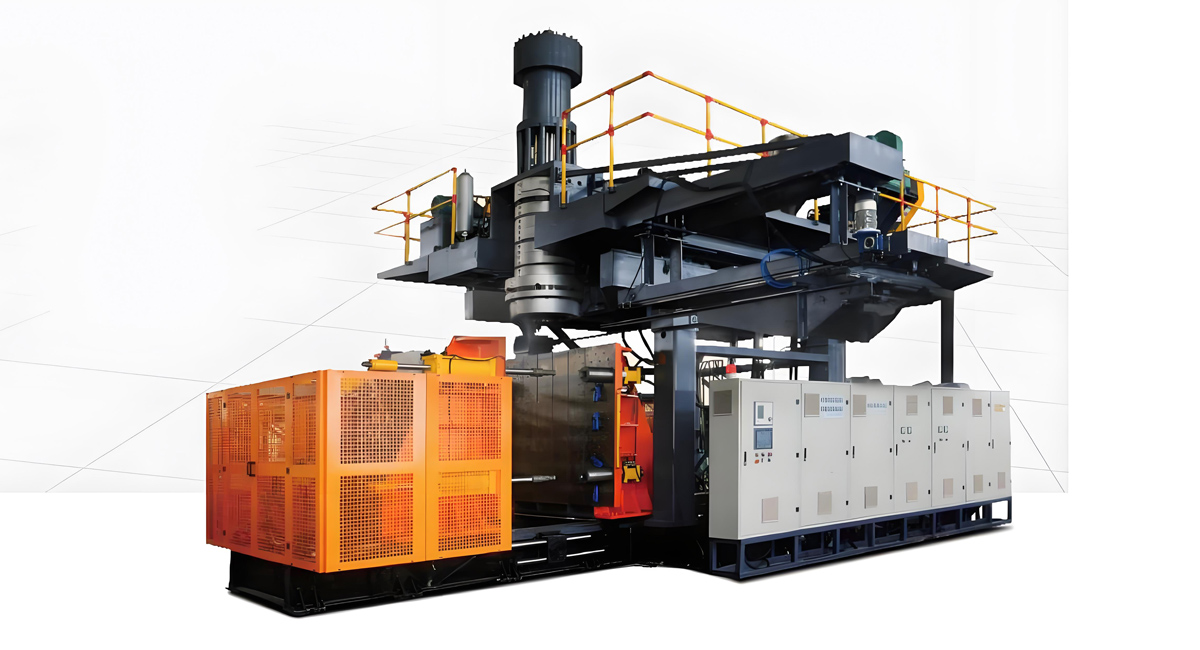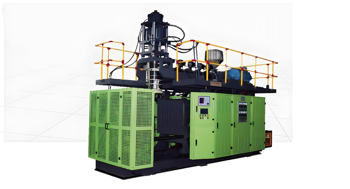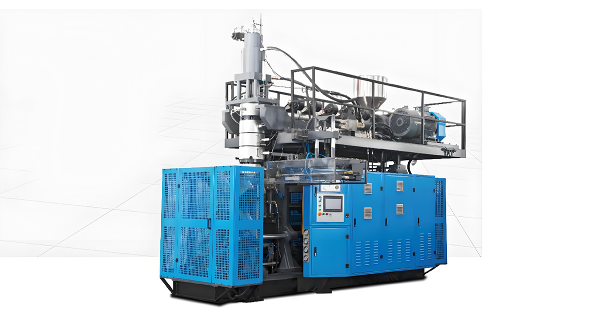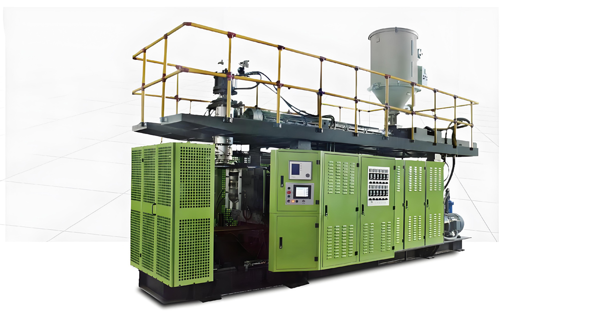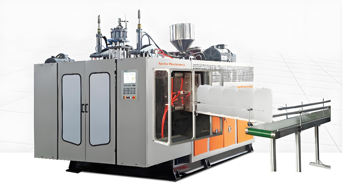
The replacement of molds for extrusion blow molding machines is the core process for achieving the production switching of multiple varieties and specifications of hollow products. It is necessary to follow the principles of “safety first, precise positioning, standardized connection, and debugging verification” to avoid equipment damage or product quality problems caused by improper operation. The following are standardized mold replacement steps applicable to mainstream continuous/intermittent extrusion blow molding machines (including fully electric, electro-hydraulic hybrid, and hydraulic types), balancing universality and practical details.
Ⅰ. Preparation work before mold replacement
1. Safety preparation and equipment shutdown
Operators need to wear protective equipment (safety helmets, cut resistant gloves, anti slip shoes), clear obstacles in the work area, ensure the performance of lifting equipment (cranes, forklifts) is intact and the no-load test run is normal.
Press the emergency stop button of the equipment, cut off the main power supply, air source, and hydraulic source (hydraulic model), close the cooling water circuit valve of the mold, wait for the equipment to completely stop running (screw to stop rotating, mold to be fully open), and hang the “mold changing, no closing” sign at the power switch.
Confirm complete release of equipment pressure: Hydraulic models need to release system pressure through pressure relief valves, while all electric motor models need to confirm servo motor power-off locking to avoid accidental action.
2. Preparation of molds and tools
Verify that the new mold model and specifications are consistent with the target product, inspect the appearance of the mold for any bumps, the mold cavity for any oil stains or damage, ensure that the cooling water channel and exhaust groove are unobstructed, and that the guide column and guide sleeve are well lubricated (with high-temperature grease).
Prepare specialized tools: torque wrench (matching mold fixing bolt specifications), Allen wrench, screwdriver, copper hammer (to avoid damaging the mold by knocking), cleaning cloth, mold positioning pin, sealing gasket (for connecting cooling water/air circuits).
Measure the thickness, weight, and installation hole spacing of the new mold to confirm its compatibility with the equipment’s mold clamping mechanism (such as mold clamping stroke, maximum mold thickness, and installation hole position matching).
3. Records of old model related data
Record the process parameters corresponding to the current old mold (mold clamping force, inflation pressure, cooling time, billet wall thickness control parameters, etc.) for easy retrieval during subsequent production recovery.
Mark the installation orientation of the old mold (such as “left mold”, “right mold”, “front/back mold”) to avoid installation misalignment when reused.
Ⅱ. Dismantling steps for old molds
1. Separate the mold from the equipment connection
If the mold is equipped with heating/cooling water and air circuits (such as blowing needle air ducts), first remove the hose or hard tube at the connection, seal the interface with a clean cloth (to prevent oil and impurities from entering the pipeline), and organize the pipeline to avoid entanglement.
Use a torque wrench to gradually loosen the mold fixing bolts in a “diagonally symmetrical” order (operate the left and right molds separately). After the bolts are completely loosened, do not remove them temporarily, only unscrew 2-3 turns to prevent the mold from suddenly shifting.
2. Lift off the old mold
Use a crane hoist (equipped with a soft sling to avoid scratching the surface of the mold) to smoothly lift the old mold. The lifting points should be symmetrically distributed to ensure that the mold is horizontally stressed. Slowly lift the mold until it separates from the guide column and guide sleeve.
A dedicated person should stabilize the mold, slowly move the lifting device, lift the old mold to the designated storage area, and gently place it on the mold rack (with wooden or rubber pads) to avoid direct impact.
Remove the old mold positioning pin and sealing gasket from the equipment’s mold clamping mechanism, and thoroughly clean the installation surface (clamping seat, template) of oil, plastic residue, and dust with a cleaning cloth to ensure that the installation surface is flat and free of debris.
3. Maintenance and storage of old molds
Clean up the plastic residue in the old mold cavity and exhaust groove, apply lubricating grease to moving parts such as guide columns, guide sleeves, and top pins, and seal the cooling water interface to prevent debris from entering.
Perform rust prevention treatment on old molds (spray rust proof oil), store them by model and specification, label them properly (including usage status and next maintenance time), and avoid collision with other molds.
Ⅲ. New mold installation steps
1. Lift in the new mold and preliminarily position it
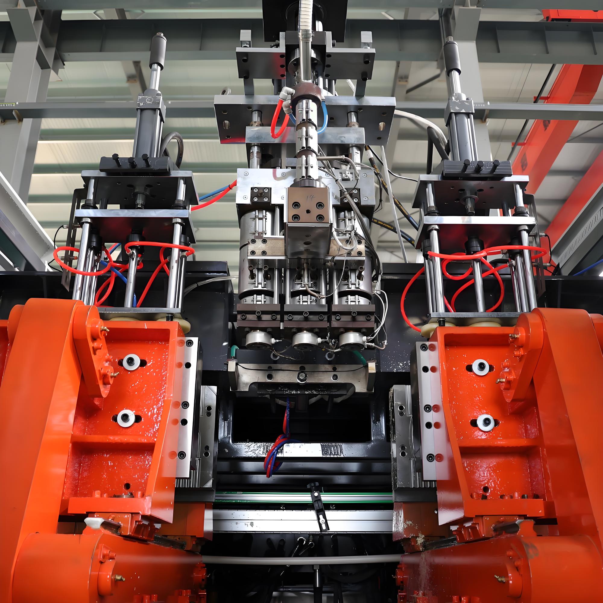
Lift the new mold steadily with a lifting device, adjust the height and angle of the lifting device, align the mold guide column with the guide sleeve of the equipment’s mold clamping mechanism, and slowly lower the mold to fit the installation surface.
Assign a dedicated person to assist in adjusting the position of the mold, ensuring that the installation holes of the mold align with the threaded holes on the equipment template. Insert positioning pins (if any) to fix the orientation of the mold and prevent displacement during installation.
Do not remove the lifting device temporarily, keep the mold slightly stressed, and use it to fine tune the position of the mold until the installation holes are completely aligned.
2. Tighten the fixing bolts of the mold
Take out the fixed bolts that match the new mold (or reuse the old bolts, check that the threads are intact), put on flat washers and spring washers, and gradually tighten the bolts in a “diagonally symmetrical” order (manually tighten first, then tighten with a torque wrench).
Bolt tightening is divided into two steps: the first step is to tighten the bolt to fit the mold, and the second step is to evenly tighten it according to the torque specified in the equipment manual (usually 25-50N · m, adjusted according to the bolt specifications), ensuring that the left and right molds are evenly stressed and not loose.
After tightening, check the flatness of the mold installation: use a feeler gauge to detect the gap between the mold and the installation surface, with a gap of ≤ 0.05mm, to avoid uneven force during mold closing that may cause mold deformation or product wall thickness deviation.
3. Connect the cooling water and air circuits
Connect the cooling water pipeline according to the mold markings (“water inlet” and “water outlet”), ensure the interface is aligned, install sealing gaskets to prevent water leakage, tighten the pipe joints, open the water valve, check the pipeline for leaks, and ensure smooth water flow.
If the mold is equipped with an air circuit (such as a blowing needle auxiliary airway, exhaust device), connect the air pipe and tighten the joint, open the air source valve, and use soapy water to check if there is any air leakage at the interface.
The connection between the mold and the servo drive mechanism (such as the engagement status of the clamping synchronous belt and gear rack) needs to be checked separately for the full electric motor type to ensure that there is no jamming.
4. Remove lifting equipment and clean up the site
After confirming that the mold is firmly fixed and the pipeline connection is correct, slowly remove the lifting device and place it back in the designated position.
Clean up tools and debris in the work area, organize pipelines and lines, and ensure that there are no entanglements or obstacles that interfere with equipment movement.
Ⅳ. Commissioning and verification steps after mold change
1. No load debugging (no raw materials, no preforms)
Connect the equipment power, air source, and hydraulic source (hydraulic model), release the emergency stop state, and enter manual operation mode.
Operate the mold closing mechanism, slowly close the mold to a semi closed state, check if the mold closing is smooth, if the guide column and guide sleeve are not stuck, and if the mold parting surface is tightly fitted (without obvious gaps).
After fully closing the mold, set the initial clamping force (usually 60-80% of the maximum clamping force required by the mold according to the mold size and product requirements), start the clamping cycle 3-5 times, and observe that the mold runs smoothly without any abnormal noise or vibration.
Operate the needle blowing mechanism, check the coordination between the needle insertion and withdrawal actions and the mold closure and opening, ensure that the needle is aligned with the center of the mold, and there is no collision with the mold.
2. Process parameter setting
Call or input the process parameters corresponding to the new mold: set the heating temperature of the material barrel and mold head according to the product material (PE, PP, PET, etc.); Set the inflation pressure and inflation time according to the product capacity and wall thickness; Set the cooling time according to the distribution of the mold cooling water circuit (usually adjusted by 5-10% compared to the old mold parameters).
Adjust the billet wall thickness control system: If it is a dynamic wall thickness control model, input the wall thickness distribution curve of the new product (such as the wall thickness parameters of the bottle bottom, bottle body, and bottle mouth) to ensure that the billet size matches the mold cavity.
3. Trial production verification
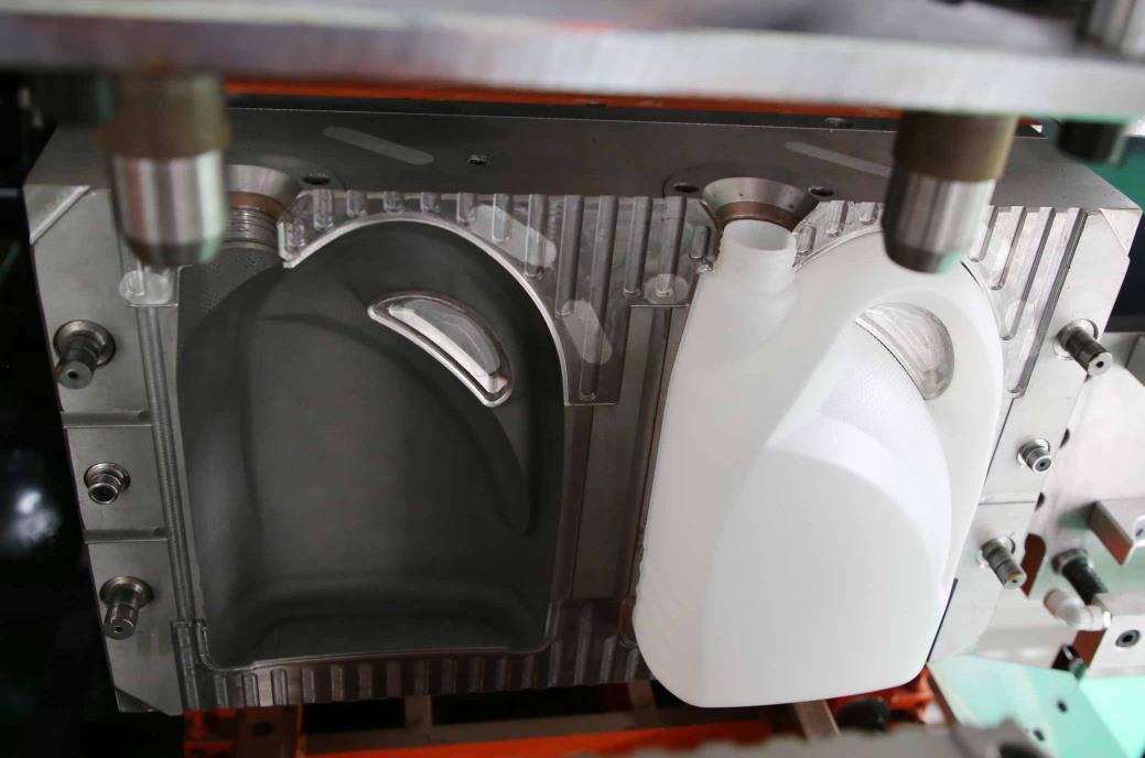
Start the equipment for small-scale trial production (5-10 products), observe the uniformity of billet extrusion, mold closure and sealing (no billet overflow), and blowing molding effect (complete product shape, no dents, bubbles, unclear patterns).
Sampling inspection of product quality: measure the uniformity of product wall thickness (deviation ≤± 3%, high-end products ≤± 1%), accuracy of bottle mouth size (clear threads, standard sealing), no burrs or burrs on the appearance, sufficient cooling (no deformation or mold sticking after demolding).
If there are product defects (such as uneven wall thickness, overflow of parting surface, difficulty in demolding), adjust parameters accordingly: adjust the billet controller or mold synchronization for uneven wall thickness; Excessive material increases the clamping force or cleans the parting surface; Difficulty in demolding: Prolong the cooling time or apply a small amount of demolding agent.
4. Batch production confirmation
Continuously produce 20-50 pieces of products, confirm that the product qualification rate is ≥ 99%, the equipment runs stably (without abnormal shutdown or leakage), and the process parameters do not need to be frequently adjusted. Then switch to automatic production mode and officially start mass production.
Record the process parameters of the new mold and save them to the equipment parameter library for easy retrieval in future use.
Ⅴ. Precautions and safety regulations for mold replacement
1. Core requirements for safe operation
It is strictly prohibited to carry out mold replacement operations before the equipment is completely shut down or depressurized, and it is strictly prohibited to operate lifting equipment in violation of regulations (such as overloading lifting, diagonal pulling lifting).
During the process of mold lifting, unrelated personnel are prohibited from staying in the work area. Operators must stand on the side of the mold (to avoid being injured when the mold falls off or tilts).
When tightening bolts, it is necessary to follow the order of “diagonal symmetry” to avoid deformation caused by uneven force on the mold; It is prohibited to directly strike precision parts such as mold cavities and guide columns with a hammer.
2. Special precautions for different models
Hydraulic model: After changing the mold, the air in the hydraulic system needs to be exhausted (through the exhaust valve) to avoid pressure fluctuations during mold closing; Check the hydraulic oil level and temperature to ensure the normal operation of the system.
Full motor type: After mold replacement, the positioning accuracy of the servo motor needs to be calibrated (through the “origin calibration” function of the equipment control system) to ensure accurate mold closure position and avoid product size defects caused by positioning deviation.
Rotary blow molding machine: When replacing multi-mode molds, it is necessary to ensure that the installation height of all mold positions is consistent and the positioning is accurate, to avoid uneven force during rotation that may cause equipment vibration.
3. Common problem handling
Mold closure stuck: Check whether the guide column and guide sleeve are missing oil or have impurities, clean them and apply lubricating grease; Check if the installation surface of the mold is flat and adjust the position of the mold.
Pipeline leakage: Replace the sealing gasket and tighten the joint again; If the water pipe ruptures, replace it with a new pipeline before running it again.
Uneven wall thickness of the product: Adjust the parameters of the billet wall thickness controller, check if the mold cooling water circuit is unobstructed, or recalibrate the synchronization of the mold closing.
The replacement of molds for extrusion blow molding machines is a systematic process of “preparation disassembly installation debugging”, with the core being to ensure safe operation, precise positioning, standardized connection, and full verification. Operators need to be familiar with the equipment structure (especially the mold closing mechanism and pipeline layout) and mold characteristics, strictly follow the principles of “diagonal symmetrical fastening”, “priority of no-load debugging”, and “trial production verification”, to avoid equipment damage or product quality problems caused by operational errors. The efficiency of mold changing usually depends on operational proficiency and equipment configuration (such as quick mold changing devices). With proficient operation, the mold changing time for single station models can be controlled within 30-60 minutes, and for rotary multi station models it can be controlled within 60-120 minutes, ensuring efficient production switching.